

GameBoy Digital Sampling Oscilloscope in 2021 ?
I remade the Nintendo GameBoy digital oscilloscope by Steve Willis from Elektor October 2000... in 2021.
I remade the Game Boy digital oscilloscope (GBDSO) by Steve Willis from Elektor October 2000... in 2021.
You might ask why I made something that's 20 years old by now and the answer is pretty simple.
Since the day I discovered the GBDSO a few years ago I wanted to build one, and so I did.
Before I go any further, everything you need to make a GBDSO is available on my github: https://github.com/pyroesp/GBDSO.
You can find the schematic, PCB, BOM list, some documentation and lots of pictures and more on the repository.
Let's review what the original GBDSO was capable of:
Very impressive features coming from a Game Boy if you ask me!
When I first contacted Elektor about this project I asked them if they still had a ROM available for a GBDSO and they had one left. So of course I had to have it and I bought it for around 10€.
Making the BOM list for the GBDSO I needed to find a few new components due to it being 20 years old:
The original MC33182D opamp wasn't available on digikey, so I went with the TL072.
The DS1267S100 100k digital potentiometer and 27C256 ROM are still available, but with a slightly different part number.
Total cost of the BOM, at the time of making, was around 31€ for 70 components.
Adding a (prototype) PCB to that from your favorite PCB fab (mine is JLCPCB) and the total price would be around 35€ to 40€.
After discussing the possibility of releasing the bin file of the ROM with Elektor, I got permission from them to upload it to my github repository making it available for everyone!
So you can build your own GBDSO for around 40€.
One addition to the GBDSO I made is the possibility to program the 27C256 ROM chip in circuit thanks to a little extension board that maps the PLCC32 ROM to a DIP32 socket and a few jumpers on the board.
It took me three hardware revisions to get it right, due to a few errors on my schematic and PCB, but it worked in the end and I couldn't be happier.
Not only do I have a GBDSO, but the whole project is available online for anyone to make.
Please visit the github repository for everything you need to make your own.
You might ask why I made something that's 20 years old by now and the answer is pretty simple.
Since the day I discovered the GBDSO a few years ago I wanted to build one, and so I did.
Before I go any further, everything you need to make a GBDSO is available on my github: https://github.com/pyroesp/GBDSO.
You can find the schematic, PCB, BOM list, some documentation and lots of pictures and more on the repository.
Let's review what the original GBDSO was capable of:
- Dual trace display
- Sampling Rate: DC to 1 Msps
- Time Base: 100 s to 5 µs/Div
- Inputs: AC/DC 1 MegOhm
- Input gain: 50 mV to 10 V/Div
- Line or chart recorder trace modes
- Real-time FFT mode with dB scale
- Variable persistence XY mode
- PC link for screen or data transfer
- 5 hrs operation from NiMH batteries
- Averaging and Auto trigger functions
- Reference trace storage
Very impressive features coming from a Game Boy if you ask me!
When I first contacted Elektor about this project I asked them if they still had a ROM available for a GBDSO and they had one left. So of course I had to have it and I bought it for around 10€.
Making the BOM list for the GBDSO I needed to find a few new components due to it being 20 years old:
The original MC33182D opamp wasn't available on digikey, so I went with the TL072.
The DS1267S100 100k digital potentiometer and 27C256 ROM are still available, but with a slightly different part number.
Total cost of the BOM, at the time of making, was around 31€ for 70 components.
Adding a (prototype) PCB to that from your favorite PCB fab (mine is JLCPCB) and the total price would be around 35€ to 40€.
After discussing the possibility of releasing the bin file of the ROM with Elektor, I got permission from them to upload it to my github repository making it available for everyone!
So you can build your own GBDSO for around 40€.
One addition to the GBDSO I made is the possibility to program the 27C256 ROM chip in circuit thanks to a little extension board that maps the PLCC32 ROM to a DIP32 socket and a few jumpers on the board.
It took me three hardware revisions to get it right, due to a few errors on my schematic and PCB, but it worked in the end and I couldn't be happier.
Not only do I have a GBDSO, but the whole project is available online for anyone to make.
Please visit the github repository for everything you need to make your own.
Discussion (4 commentaire(s))
richfiles il y a 3 ans
I had a minor accident with my phone in the summer of 2020, and it severely damaged my charge port. Rather than give up on the phone and replace it, or go phoneless till I could have replacement parts shipped, I chose to repair the charge board. It involved reflowing a chip that had popped off the board, and rewinding a cracked inductor and soldering it back into place. This was all done under a microscope, for obvious reasons. The topic of SMD soldering got brought up, and I decided to drag this old kit out and take a photo and a video of it.
Hopefully someone else will enjoy the trip down memory lane. Great to see this rejuvenated, if anything as a nostalgic kit. I'm just as glad to see modern scopes come down to prices even a hobbyist can afford. It's really wild how far easy to access, feature filled, and especially how low cost tech has come in the past two decades!
https://www.youtube.com/watch?v=AQ_Gj7t3MSU
Hagen Patzke il y a 3 ans
JRodrigo il y a 3 ans
Just say thanks to you, I will be able to finally build it =D
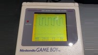
The square wave on the screen looks a little bit noisy, perhaps cleaning the board can eliminate some or all the noise, because flux residues can create leakage paths of a few nanoamps enough to add error to a megohm resistor.
Kabron il y a 3 ans
GBA is.