Article
i-Pendulum
2e partie – logiciel, assemblage, tour de contrôle

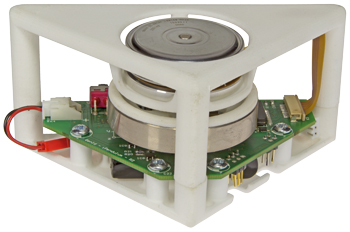
Après la théorie, place à la pratique ! Cette seconde partie vous guidera dans la construction de votre pendule inversé. Une fois le câblage du circuit électronique et l’assemblage des pièces mécaniques terminés, vous pourrez ausculter le cœur du pendule avec le logiciel sous Windows prévu à cet effet.
Info supplémentaire / Mise à jour
Download; https://www.elektormagazine.com/labs/inverted-pendulum-150175-i
Liste des composants
Résistances
(CMS 0805, 0,125 W, 1% sauf mention contraire)
R1, R21 = 10 kOHM
R2 = 330 OHM
R3, R4, R5, R22 = 130 OHM
R6 = 100 OHM, 1206, 0,25 W, 1%
R7 = 100 kOHM
R8, R9, R10, R11 = 1 OHM, 1206, 0,25 W, 1%
R12 = 56 kOHM
R13 = 11 kOHM
R14, R20 = 20 kOHM
R15, R26 = 24,9 kOHM
R16, R17, R18 = 4,7 kOHM
R19 = 1 kOHM
R23 = 215 kOHM
R24 = 15 mOHM, 2512, 1 W, 1%
R25 = 160 kOHM
Condensateurs
(CMS 0805, 50 V, 10% sauf mention contraire)
C1, C37, C40 = 10 µF, 16 V, 1206
C2, C3, C4, C5, C6, C7, C8, C10, C21, C22, C23, C25, C26, C30, C31 = 100 nF
C9, C11, C12, C17, C24, C36, C39 = 10 nF
C13, C15, C33 = 220 nF
C14, C29 = 68 µF, 16 V, 20%, 0,05 ?, SMD-D
C16 = 5,6 nF
C18 = 1,2 nF
C19 = 33 nF
C20, C32, C35, C38 = 1 µF
C27, C28 = 47 µF, 10 V, 20%, 0,035 ?, SMD-D
C34 = 100 pF
Inductance
L1 = inductance blindée de forte puissance – 5,0 µH
Semi-conducteurs
D1, D2 = 1N4148W
D3 = MBRS340T3G
LED1 = LED, CMS, 1206, rouge
LED2 = LED, CMS, 1206, jaune
LED3, LED4 = LED, CMS, 1206, vert
IC1 = dsPIC33EP128MC202-I/SS, échantillon Microchip
IC2 = SN65C3221E
IC3 = L6235PD
IC4 = ADXL345BCCZ
IC5 = SN74AHC1G32DBVT
IC6 = ISZ-2510
IC7 = MAX668
IC8 = LP2985-33DBVTE4
IC9 = LP2992IM5-3.3/NOPB
T1 = FDS6680AS
Divers
F1 = fusible, 8 A, 125 V, CMS
K1 = embase, 2x2, pas de 2,54 mm
K2 = embase, 2x3, pas de 2,54 mm
K3 = connecteur FFC/FPC, ZIF, 11 points, pas de 1 mm, à angle droit
K4 = connecteur S2B-XH-A
S1 = commutateur à glissière, SPDT, à angle droit
Circuit imprimé
M1 = moteur plat, Maxon EC 45, Ø 42,9 mm, sans balais, 12 V, 30 W, avec capteurs à effet Hall
BAT1 = batterie LiPo, 7,4 V, 2S, 30 C, 450 mAh
Pièces mécaniques
Demi-coque du circuit imprimé, imprimée en 3D
Demi-coque du moteur, imprimée en 3 D
Moyeu de la roue d’inertie, imprimé en 3D
Roue d’inertie, Ø externe = 55 mm, Ø interne = 48 mm, H = 10 mm, AWSM-D-D55-V48-T10 de Misumi
Vis pour moteur, M3, 6 mm
Vis pour demi-coques et circuit imprimé, NO6X1/2
Câble d’adaptation pour la batterie
Câble d’adaptation pour la batterie
Connecteur RCY - contacts mâles à sertir + boîtier
Connecteur XH – contacts femelles à sertir + boîtier
Fil AWG 20, rouge, 40 mm
Fil AWG 20, noir, 40 mm


Discussion (0 commentaire(s))