XMAS

The color led Xmas tree lighting I bought showed a very poor lightshow. I wanted a smooth fade-in and fade-out in different speeds, exploding stars..
2 years ago I bought color led xmas tree lights. It showed some fast and slow flashing but not much more. I opened the casing and discovered that the AC from the wall transformer was rectified without a capacitor. Two small thyristors are used to switch on and off the red/yellow and the blue/green led strings. Apparently the program and the setup are usable for small bulbs but certainly not for leds.
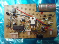
I decided to use an AtTiny44 and two PWM channels to do a better job. The following applies to tree lights with 240 leds, divided into 12 strings of each 5 red/5 yellow and 5 blue/ 5 green leds. My circuit has the same input and output as the original controller : two lines from the wall transformer and tree lines to the leds : common anode, red/yellow and blue/green.
The fully rectified input voltage was more than 40 volts, so I reduced it to 30 Volts with an LM317, mainly to accomodate for the output transistors I intended to use. The red/yellow strings (on OC1A) needed about 3 mA for an adequate light level, while the blue/green strings (on OC1B) only needed 1mA (*12), so the LM317 needed no cooling, nor the output transistors, resp BSS138 and IRLD024. The output transistors are absolutely not critical. They should withstand at least the 30 volts, the expected dissipation, and have a Vgs of less than 4Volt.
The other transistors are not critical either, even BC108's will do ;)
I found that after fade-out the leds were still visible, so I inverted the PWM signals and added a red and a green led for testing purposes. As in the original controller a pushbutton (from PB0 to Gnd) allows to switch between programs. The selection is kept in eeprom.
The program is essentially an interpreter so that I could rapidly test and adapt all effects, combinations, durations, sequences and the random generator. The input table can be found in the attachments. It was devised so that the setting of the bits is both readable by a myself and by the assembler.


Mises à jour de l'auteur