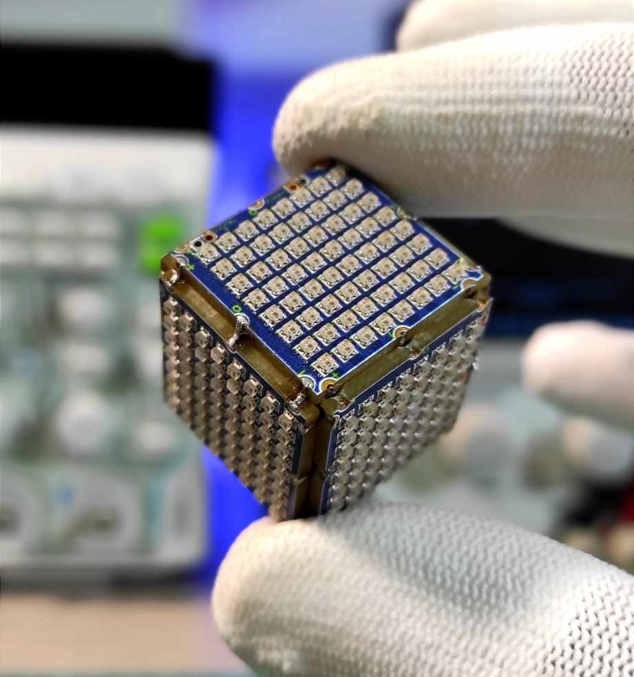
Welcome to my tutorial on building what might be the world’s smallest RGB LED Cube! In this project, I’ll walk you through the entire process of designing and assembling an ultra-compact LED cube, containing 384 individual addressable RGB LEDs, packed into an 8 cubic centimeters layout. This cube is powered by an ATmega328 microcontroller and uses WS2812B LEDs, giving you endless possibilities for lighting effects and animations.
Whether you're a beginner or an experienced maker, this project will challenge your soldering skills and creativity. Follow along, and by the end of this guide, you’ll have your very own miniature RGB LED cube displaying vibrant animations.
Supplies
Here’s a list of everything you’ll need to build the cube:
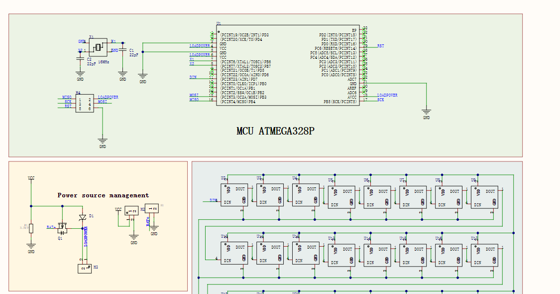
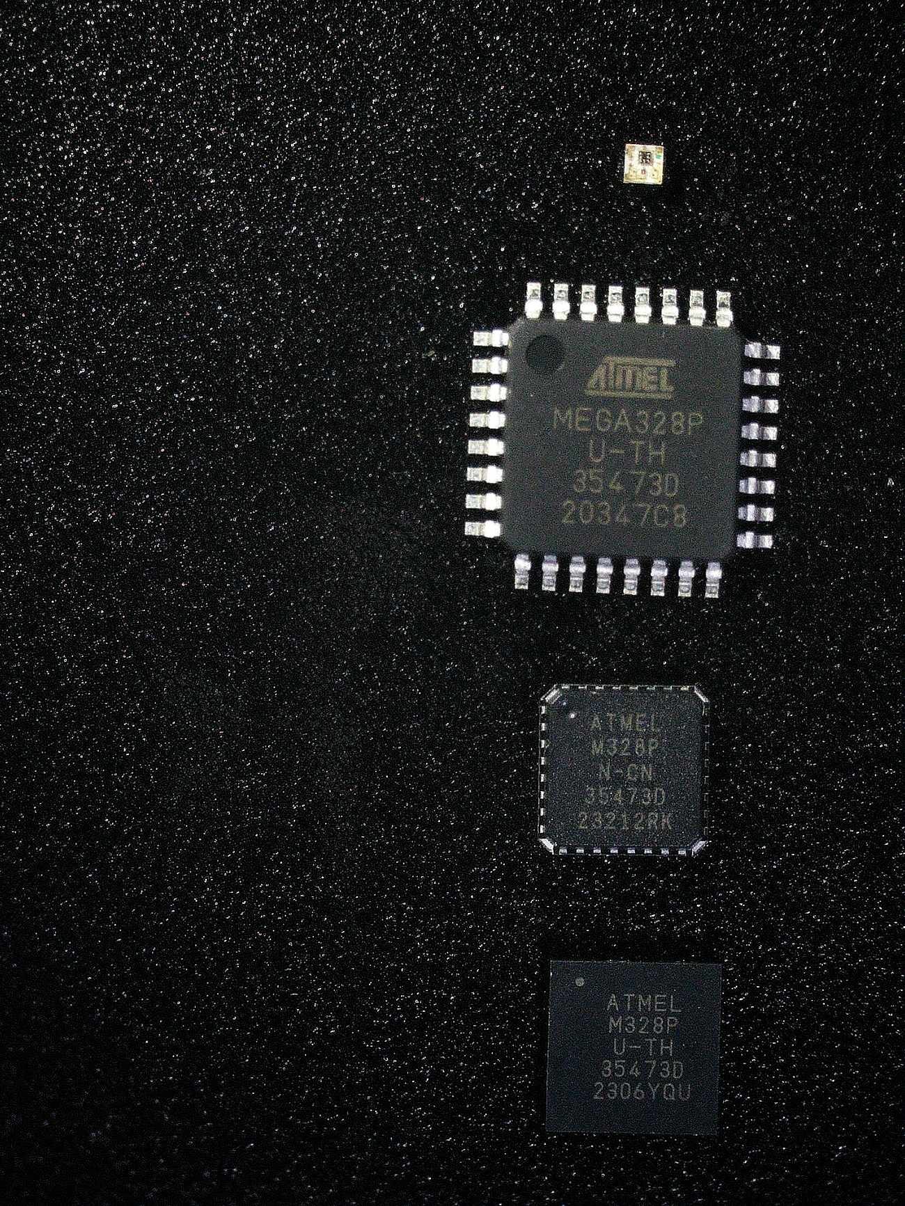
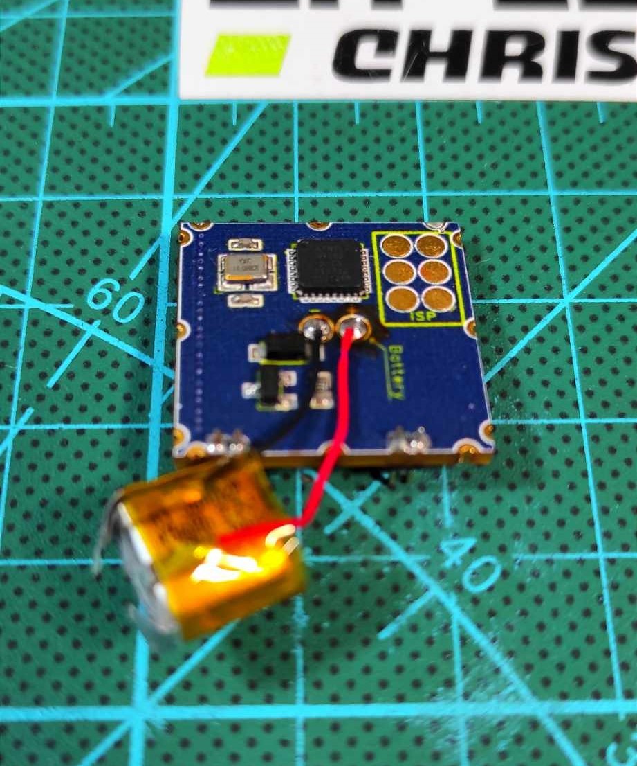
The core of this RGB Cube is the ATmega328p microcontroller paired with WS2812B-1010 addressable RGB LEDs. The ATmega328p was chosen for its Arduino compatibility and sufficient I/O capabilities, while the WS2812B LEDs allow for daisy-chaining control, requiring just one pin to handle all 384 LEDs.
Power and Circuit Design:
The cube is powered by a 3.7V lithium battery.
The ATmega328p runs at 5V with a 16MHz crystal oscillator for stable operation.
Using Altium Designer, I created a compact schematic, keeping trace lengths short and adding bypass capacitors to reduce noise. I also optimized power usage through code, ensuring the cube can handle vibrant animations without overloading the system.
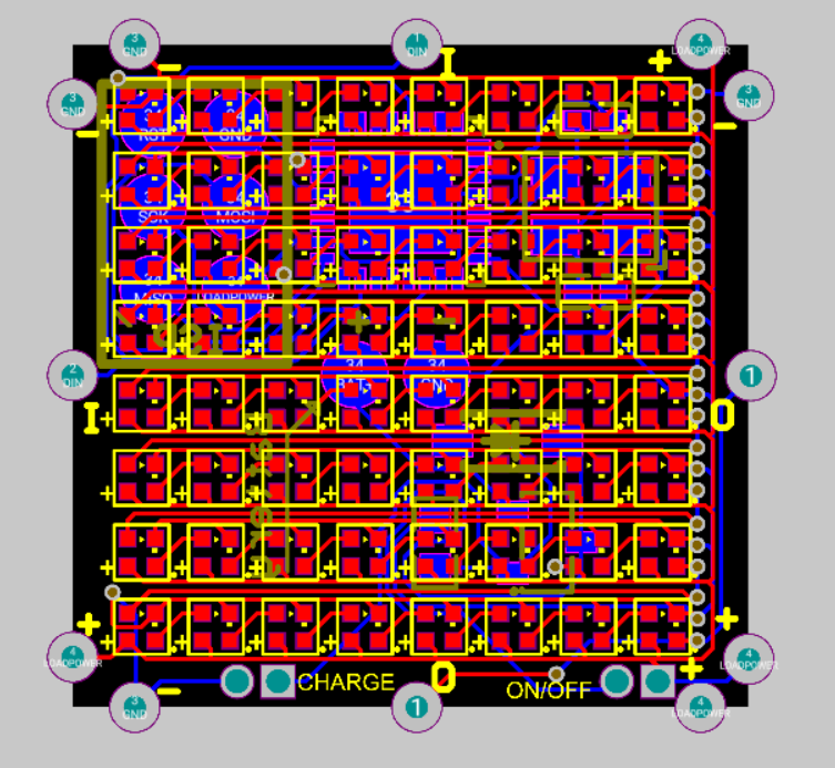
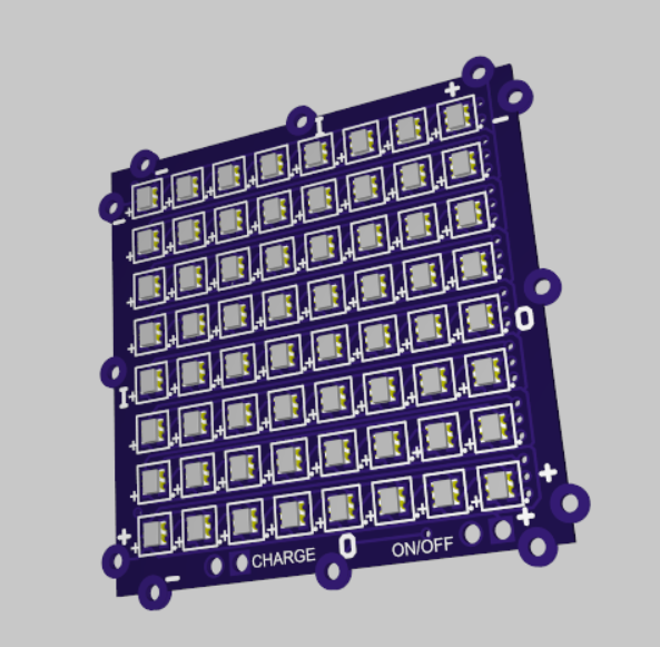
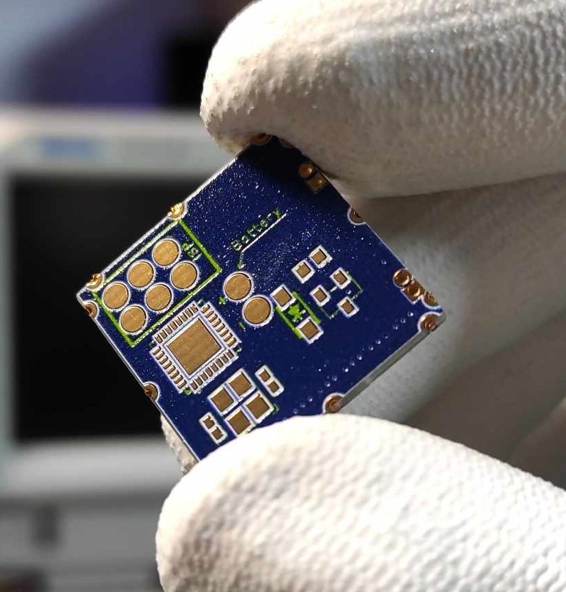
Designing and Manufacturing the PCB With the schematic complete, it was time to move on to the PCB layout. The goal was to fit 384 tiny 1x1mm WS2812B LEDs onto an 8 cubic centimeter cube, so space optimization was key. Using Altium Designer, I carefully placed the components and routed the traces to ensure smooth data and power flow across the entire LED array.
PCB Design:
I created a 2-layer PCB to accommodate the high density of components while keeping the board compact.
To ensure reliable connections, I routed ground plane separately from the signal traces, reducing electrical noise.
The ATmega328p microcontroller was placed at the center, allowing short signal traces to all LED arrays.
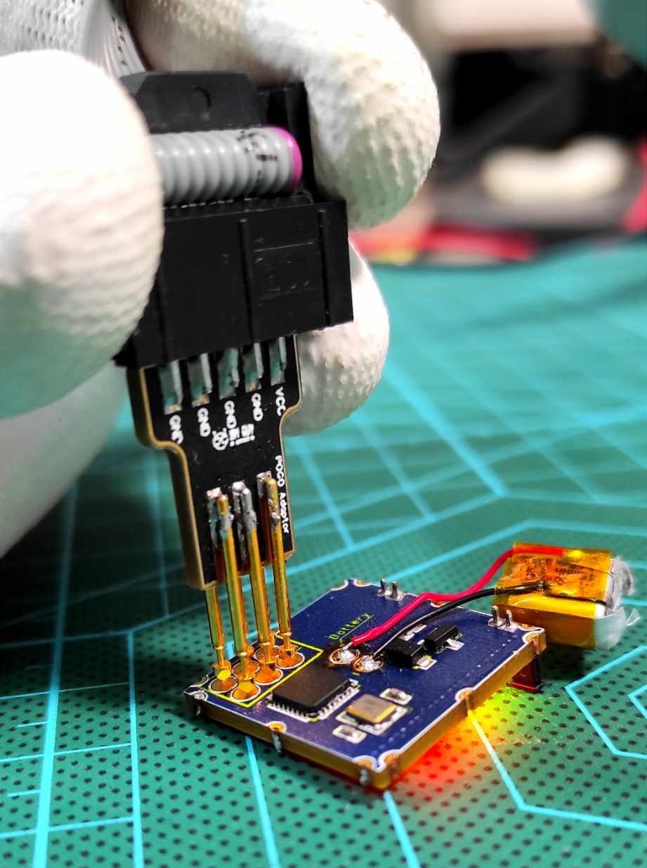
I also added mounting pads for a 1.27mm pitch header to allow easy reprogramming and power connection.
Manufacturing:
Once the PCB design was finalized, I uploaded the Gerber files to JLCPCB, who handled the manufacturing. Their precision fabrication and affordable prices made them an excellent choice for a small, complex project like this.
After receiving the boards, I performed a quick inspection to ensure the traces and solder mask were clean and accurate. Everything looked perfect, so I was ready to move on to assembling the components.
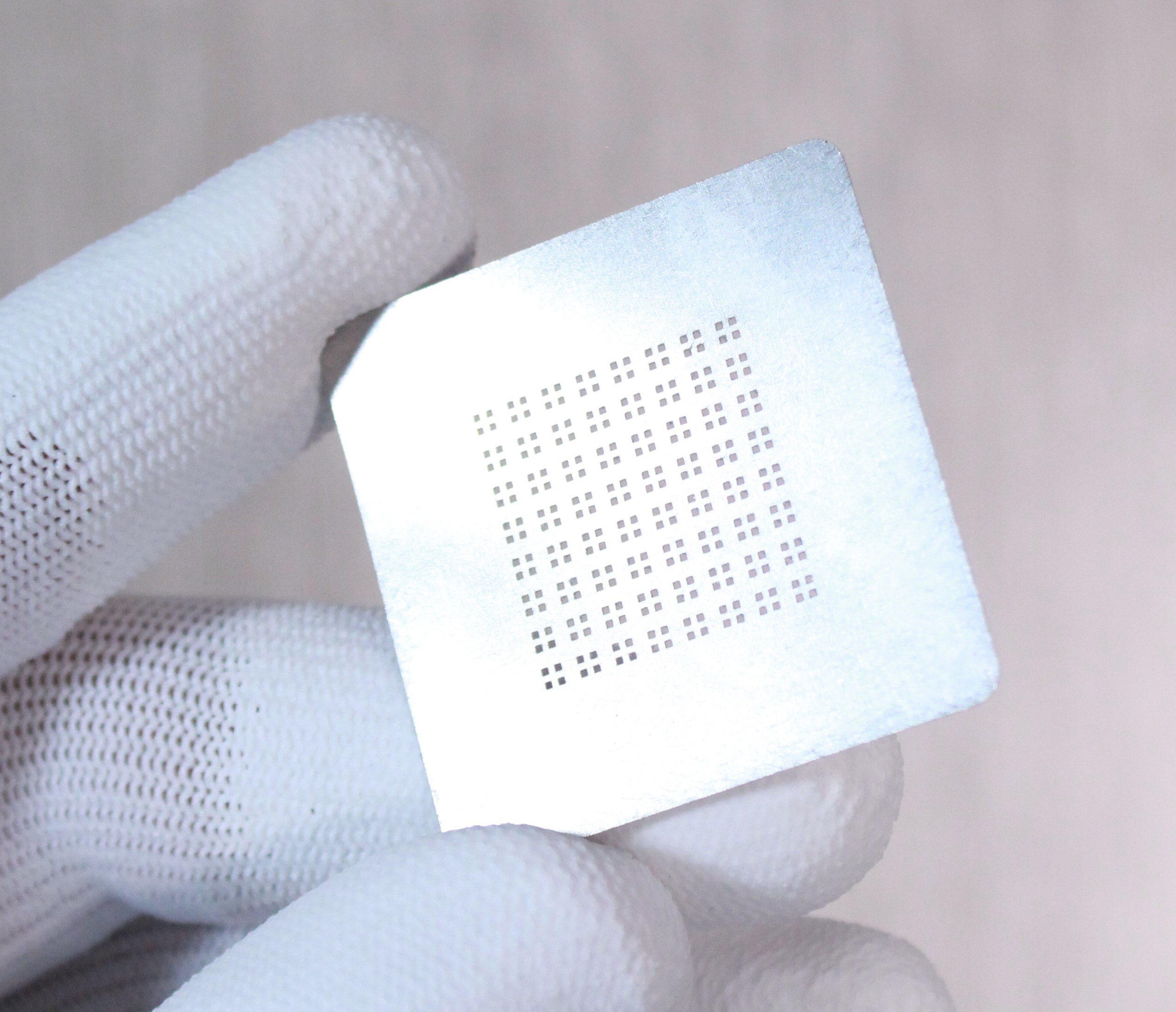
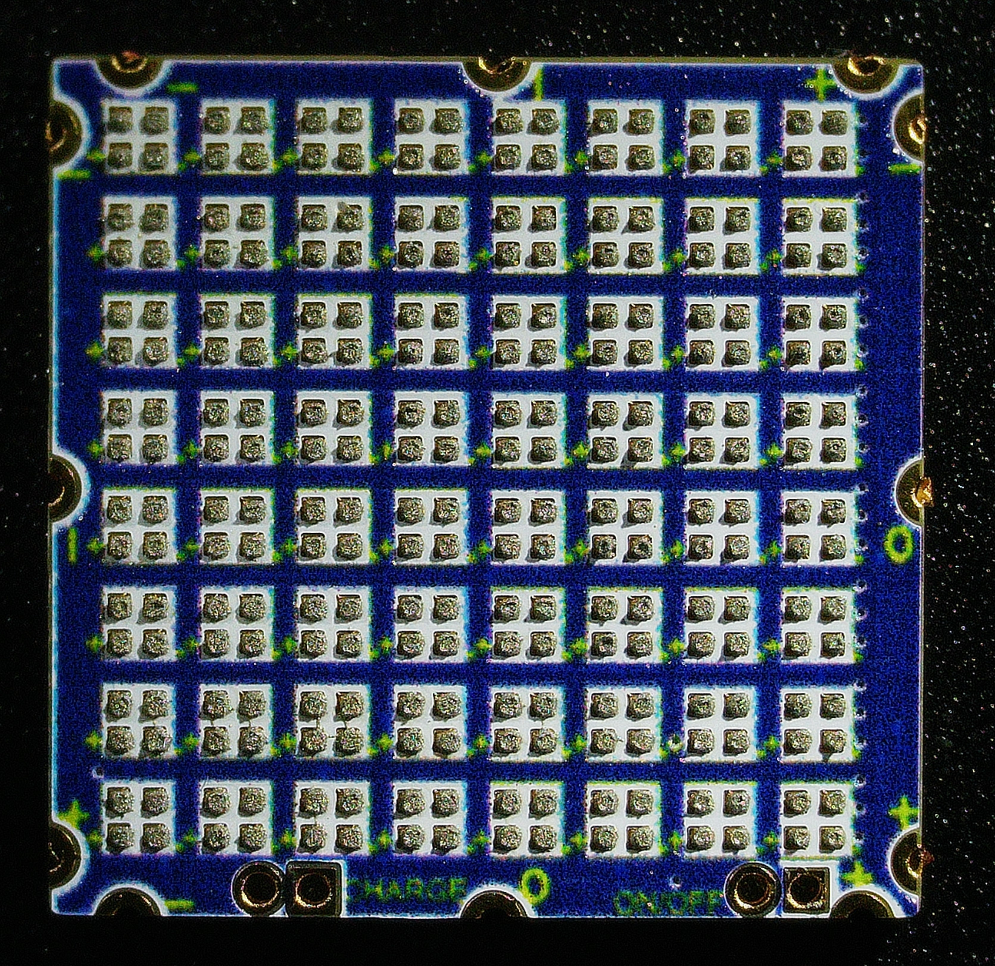
Soldering the LEDs and Components For this project, I used a hot plate to reflow the solder paste and attach the LEDs and components. These 1x1mm WS2812B LEDs are incredibly small, so using the stencil was essential for applying solder paste evenly.
Here’s a detailed guide on handling these tiny components and ensuring a solid connection:
Use fine-tipped tweezers for placing LEDs.
A microscope will help with inspecting your solder joints.
A flux remover will help clean up any excess solder and ensure clean connections.
If you prefer soldering by hand, then you can only solder the bottom side components, as for the LEDs it is not possible to solder them by hand. Programming the LED Cube
With the hardware complete, it’s time to program the cube. The ATmega328 microcontroller runs the show, and I programmed it using the Arduino IDE. The code drives animations across the 384 LEDs, creating dynamic light patterns.
You can download the Arduino code I used from the link below. Feel free to modify it or create your custom animations!
You’ll need to burn the bootloader onto the ATmega328p.
To program, I used a simple ISP programming technique, which you can learn about here.
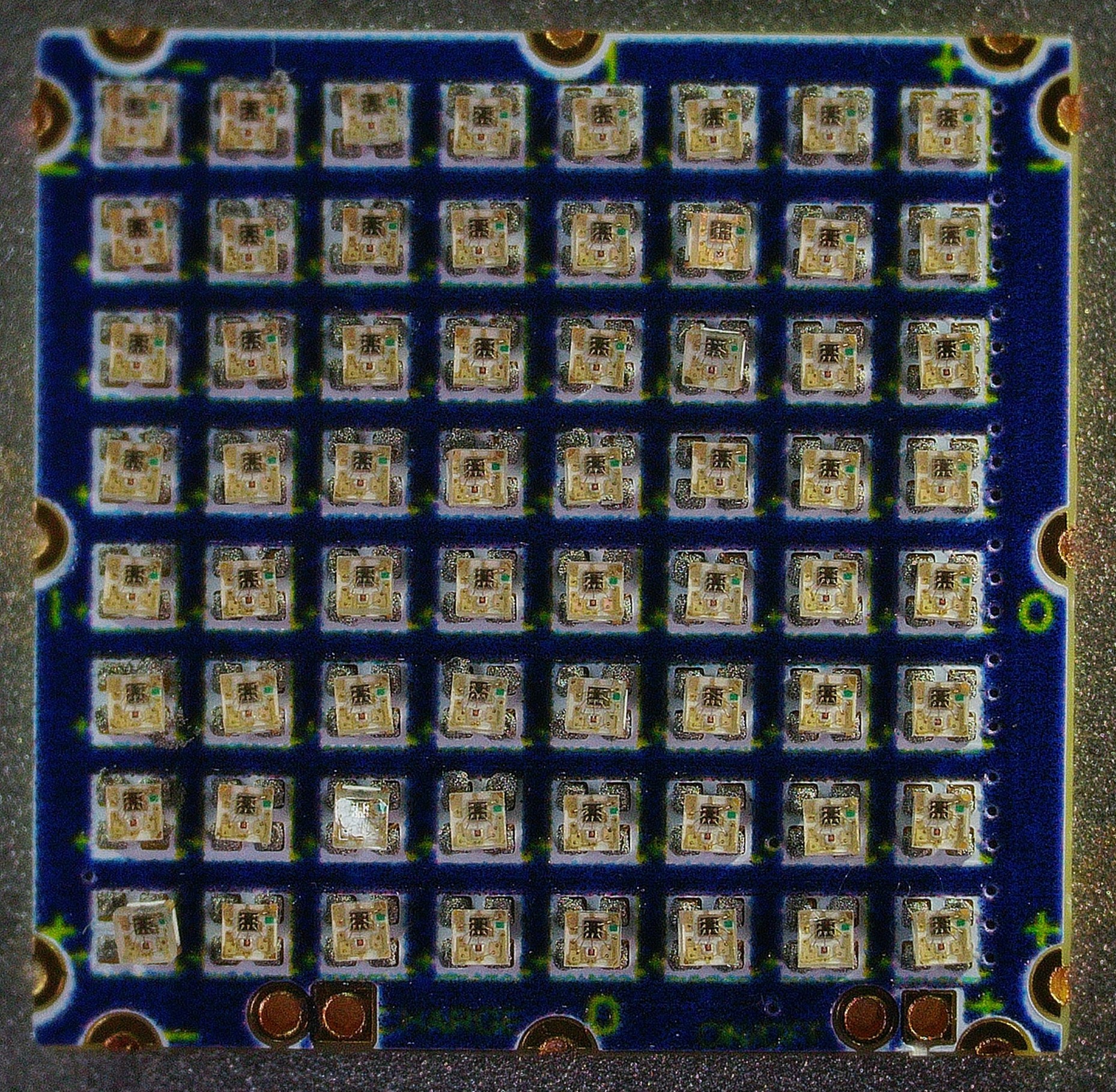
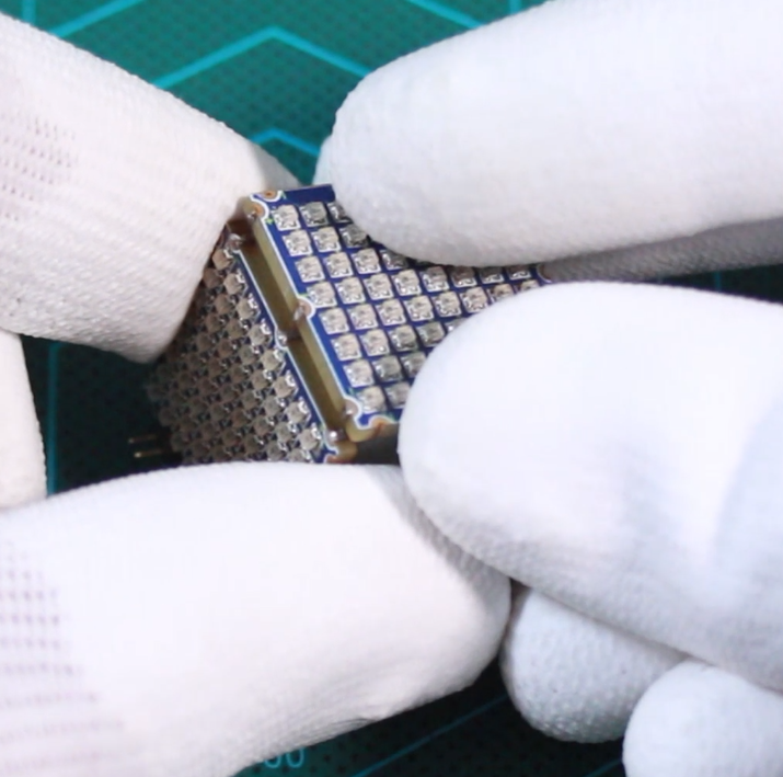
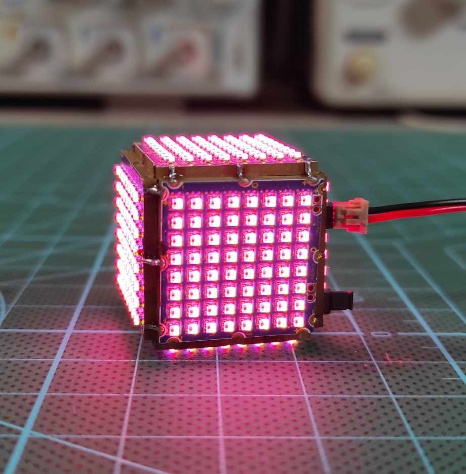
Assembling the Cube and Final Testing The final step is assembling the cube. I 3D printed a simple assembly aid to hold the LED layers in place while soldering them together. Once the cube was fully assembled, I tested it to ensure all LEDs functioned properly and that the animations displayed as expected.
I encountered a few challenges along the way, mainly with aligning the LEDs matrices perfectly, but once completed, the results were incredible. You now have a tiny RGB LED cube capable of displaying beautiful, vibrant animations!
Final Thoughts
This tiny RGB LED cube project is both a fun and rewarding challenge. Whether you’re new to electronics or a seasoned hobbyist, it’s a great way to practice fine soldering skills, PCB design, and power management for small-scale electronics. Plus, the end result is a mesmerizing cube full of vibrant color animations!
I hope this tutorial helps you in your journey to create your LED cube. Don’t forget to share your thoughts, ask questions, and show off your creations in the comments below!
Veuillez saisir votre adresse électronique. Les instructions de réinitialisation de votre mot de passe vous seront immédiatement envoyées par courriel.


Discussion (2 commentaire(s))