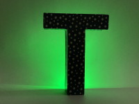
The Tranquili-T

An object that creates a calming atmosphere of sound and light effects
Often a hobby electronics engineer with his great circuit projects remains quite unnoticed by his family and friends. The understanding and the appreciation of non-electronic engineers for e.g. a self-built oscillator or a servo control is not very big . However, I have always received a lot of praise and appreciation for my Tranquili-T (in German: Beruhigungs-T = calming Tea). And so I have already built many of them for friends and relatives. These MP3 players, which are housed in a beautiful case, play e.g. bird calls or sea noise in the background. The calming and relaxing effect is additionally supported by an integrated rainbow LED, which can spread a very beautiful lighting mood in a darkened living room. Beside the obvious play on words, the T-shape of my objects resulted at the first time from combining a tube-shaped USB power bank with a piece of plastic tube for the player, the speaker, the switches and a USB-plug. For the larger objects I then modified cheap T-shaped cardboard letters. The housing is quickly processed and can be covered with decorative adhesive foil or gift wrapping paper.
This Tranquili-T video lets you see and hear one of the results in action.
Here a making-of-Video.
More Fotos at https://peterneufeld.wordpress.com/2020/08/17/the-tranquili-t/
The electronic parts are wired without a printed circuit board. In some cases it was useful to set some or all of the parts on a hole grid board.
The circuit of all objects consists of a combination of five function blocks, which can be adapted to the respective needs (or to the content of the tinkering box):
More about this project at https://peterneufeld.wordpress.com/2020/08/17/the-tranquili-t/
This Tranquili-T video lets you see and hear one of the results in action.
Here a making-of-Video.
More Fotos at https://peterneufeld.wordpress.com/2020/08/17/the-tranquili-t/
The electronic parts are wired without a printed circuit board. In some cases it was useful to set some or all of the parts on a hole grid board.
The circuit of all objects consists of a combination of five function blocks, which can be adapted to the respective needs (or to the content of the tinkering box):
- Power supply (e.g. 5V-USB-power bank or also 3* 1.5V dry batteries)
The use of a power bank can be helpful, because you don’t have to worry about a possibility to change the empty batteries. In the simplest case the power bank and the player head are plugged together to activate the object. The battery should have at least 500mA/h for the LED with about 20mA and the player with about 50mA at moderate sound volume. - Rainbow LED
A 5mm-LED with automatic continuous colour change. R3 limits the current (and brightness) and should be between 150 and 220 Ohm, - MP3-Player
Small, cheap MP3 players in various small designs with integrated Class D speaker amplifiers have proven themselves. They either have a small own memory on board (e.g. JQ6500-16P with 4Mbyte) or are equipped with a micro-SD card slot (JQ6500-28P, DF-Player-Mini, DF-Player).
Somewhat problematic is the autostart of the player at power-on. For this purpose, the JQ6500-P16 must be fitted with an additional 33K resistor on the board, for example. The DF-Player-mini allows a third button at pin ADkey1 to endlessly play all files in a corresponding section/directory. But in the simplest case, it is sufficient to press the „Vol+“-button after power-on to start the player with the first file in the FAT. - Speaker
The loudspeaker is usually as flat and small as possible – depending on the cabinet – with at least 0.5W, 8Ω to 32Ω. 4Ω speakers turned out to be too loud. - Switches/buttons for „V- , <“ and „V+, >“ and possibly also for „ON/OFF“
Mostly small push buttons are suitable here, but in the best case they hardly have to be pressed at all, because the MP3 module automatically plays exactly one MP3 file at a good volume when started. The schematic shows marked in BLUE the combination of two control buttons and two digital input-pins. Alternatively marked in RED the version with only one analog input-line and a switched bank of specific resistors for the different functions (R1=3k3, R2=6k2 for JQ6500). In the course of time I have built up different versions of the Tranquili-T. Hopefully, the photos give a good impression of them and a suggestion for own setups.
More about this project at https://peterneufeld.wordpress.com/2020/08/17/the-tranquili-t/


Discussion (0 commentaire(s))