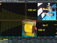
Simple tool to assess inductors and transformers with 100nH < L < 100H+

- Have an unknown inductor/transfomer? - A digital scope ..then with a tiny simple circuit and a pocket calculator you may quickly get the inductance, number of windings amount of losses using a tiny circuit in addition. Here it is described how !
A well known method to quickly get informations on the inductance L and losses of coils, transformers or other inductors is to combine them with a known capacitor to form a resonator. From the resonance frequency f one may infer the value of L. The resonance my be searched by scanning with a signal generator, using the resonator in an oscillator circuit or kicking the oscillation and observing the resulting damped oscillation. Here I will describe a tiny circuit to perform the latter method and illustrate its application with a few examples. Besides the simple "kicker" circuit (for less than 10 Euros) the method requires a digital oscillosope, which any professional and probably many hobby electronicians will have on their benches.
The method is old.
In the detailed description a very simple but versatile circuit is shown to support this method and examples are given of what can be measured and how.
This covers a small 8 turns copper coil 300 nH up to and 8000 winding transfomer core with 100 H. The only parameter to be adapted is the time base of the oscilloscope.
The description, the schematics and the examples with traces and results all are shown in the attached description.


Discussion (2 commentaire(s))