Sceptre meets Arduino [100609]

When the Sceptre was being designed, the idea of using it with a resistive touch screen had already been considered. Here is the implementation.
Sceptre: Driving a Touch Screen Arduino-style
It’s not hard to find inexpensive replacement resistive touch screens for the Nintendo DS games console on the Internet. When the Sceptre was being designed, the idea of using it with this type of touch screen had already been considered — indeed, that’s why a space was left between connectors K6 and K7 (to run the connecting wires).
This is article is part of a large project published in 2010 & 2011 covering several articles:
- The Sceptre - hardware (main article)
- The Sceptre - software
- Debugging the Sceptre over JTAG
- The InterSceptre - I/O expansion board
- The Sceptre meets Arduino (this article)
- The Sceptre meets Oberon
- Graphic display shield for the Sceptre
When designing a board, lots of things are often planned for, but not necessarily all implemented. Thus one of the things planned was a library for programming the Sceptre like Arduino, i.e. using a ‘sketch’, a ‘loop’, and a number of reconfigurable (input/output) ‘pins’. So why not drive the touch screen in this Arduino manner — thereby killing two birds with one stone? Well, that’s just what we’re going to do here.
A resistive touch screen is nothing more nor less than two X and Y potentiometers whose wiper positions are determined by the position where you press on the screen. The potentiometers are powered in turn and the wiper voltages measured. Two measurements X and Y are all it takes to find the position (x,y) where it is being pressed. In practice, each potentiometer actually has a pair of wipers, which are the contacts of the other potentiometer. When a voltage is applied to the X potentiometer, the voltage is read off one of the two Y potentiometer contacts, and vice versa. Thus when driving this type of screen, the ports driving the X and Y potentiometers are constantly changing roles: at one moment they act as outputs to apply a voltage to the potentiometer, and the next moment they act as analogue inputs to measure the wiper voltage.
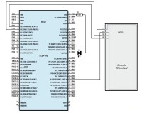
So to drive a resistive touch screen with only four ports, the ports need to be reconfigurable. On the Sceptre, the plan was to use ports P0.13, P0.15, P0.21, and P0.22 (which also offer ADCs AD1.4–AD1.7) for driving a touch screen. It’s not hard to connect up the screen to the Sceptre. You can use the special miniature Nintendo DS connector (which can be found on the Internet), but you can also just solder the wires directly onto the screen’s flexible PCB, after scratching off a bit of the varnish at the point where this flexible PCB is at its widest.
Programming Arduino-style
To start off, we have renamed the Sceptre’s usable ports to obtain a total of 45 ‘pins’. Then, a table was drawn up showing these pins and the corresponding possible functions they can have, which enables us to find out if a certain pin can be used for a certain function. PIN4 for example can be used as a digital input, digital output, analogue output (a real one!), and an analogue input. Now, in the software, we can declare a digital output like this pinMode(PIN37,OUTPUT) and if PIN37 is capable of fulfilling this function, it will be a digital output. The digitalWrite(PIN37,HIGH) function then allows us to set a high on PIN37; the digitalWrite(PIN37,LOW) function sets it low. For the analogue side of things, just as in Arduino, a pin becomes an analogue input (output) (if this is possible, of course) as soon as we go and read from it (write to it).
Driving the touch screen now becomes simple:
pinMode(PIN2,INPUT);  // Y0 digital input
pinMode(PIN1,OUTPUT);  // X0 digital output
pinMode(PIN29,OUTPUT);  // X1 digital output
digitalWrite(PIN29,HIGH);  // X1 → high
digitalWrite(PIN1,LOW);  // X0 → low
value = analogRead(PIN33);  // Read voltage on “wiper” Y1
Then repeat these instructions, but changing PIN1 to PIN2 and PIN29 to PIN33 to obtain the other co-ordinate.
Note that even when reading only one analogue input (Y1), the potentiometer’s other pin (Y0) must be disconnected from the screen in order to avoid the measurement’s being influenced. This is why is has been declared as a digital input.
A number of Arduino-style analogue outputs, i.e. 490 Hz PWM outputs, have also been implemented.
In order to communicate with a computer like an Arduino, the functions Serial_begin, Serial_write and Serial_write_int are available. The difference in the notation compared with Arduino is simply due to the fact that the Arduino library for the Sceptre is programmed in C and not C++.
In order to simulate an Arduino ‘sketch’, we first call the setup function from main, then main will periodically call the loop function from an endless loop. Take a look at the sketch.c file to see just how close the result is to a real Arduino sketch.


Discussion (0 commentaire(s))