Repair of a Rohde&Schwarz SML03 RF signal generator
Repair a 200 Euro display unit with just 10 Euro worth of components
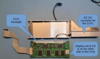
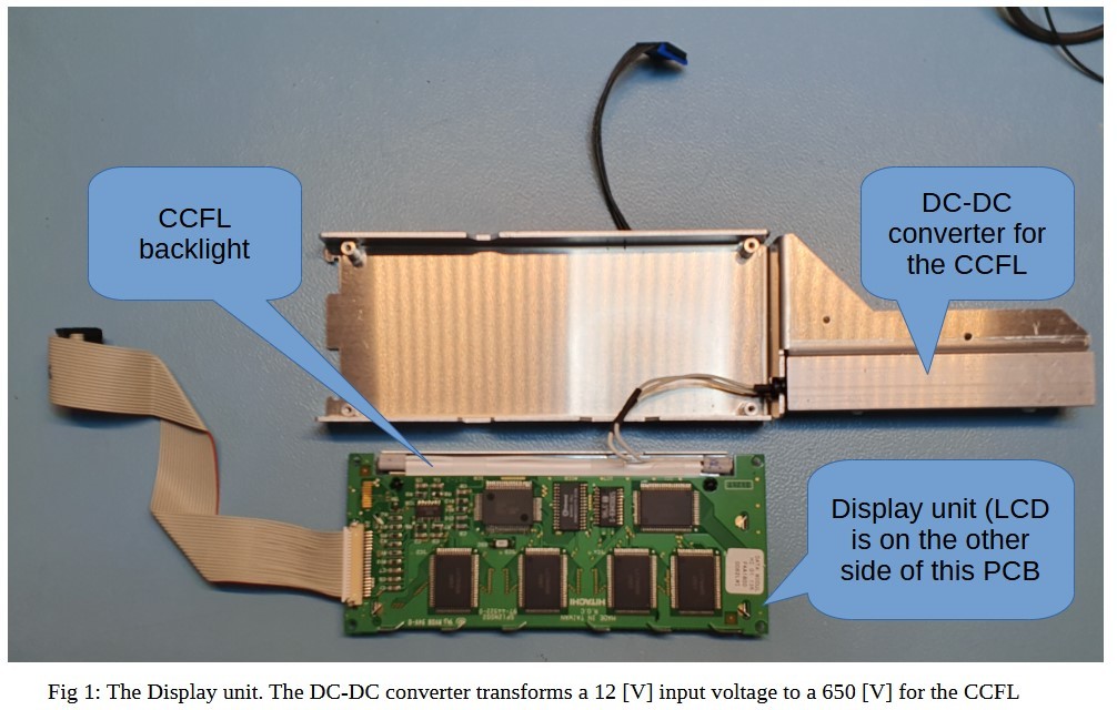
Introduction Some time ago I got my hands on a broken Rohde & Schwarz SML03 signal generator. Such a professional instrument is a valuable piece of equipment, so worth trying to repair. This is the story how I got it running again including design of a new circuit. The problem: CCFL After switching on I noticed no smoke and a fan that started. The display was dead, however on closer inspection some very faint numbers were visible. After some googling, it was most obvious that the backlight of the LCD display was the culprit. In this case the backlight is a tiny glass-tube with a diameter of 3.4 [mm] and a length of approximately 125 [mm]. It is a CCFL (Cold Cathode Fluorescent Light). The complete display unit is the LMG7380QHFC and prices vary between 200 to 300 Euro (Fig 1). An obvious question popped up: can it be repaired for less money? In the specification document of the complete display unit there is no mentioning of a specific CCFL tube to replace the old one. Again after some research on the internet I found the idea of replacement with a LED strip the most attractive solution.
The solution: LED-STRIP
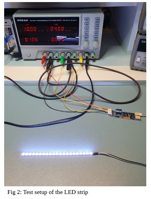
Instead of designing a LED strip, for less than 10 Euro one can buy one in the familiar Asia web-shops. It comes including a DC-DC converter. The one I bought had dimensions of(LxDiam) 485 mm * 4 mm, and very important: it could be trimmed to the desired length. After using sharp cutting pliers its length was reduced to approx 125 [mm]. The DC-DC converter has an extra input, for regulating the current for the LEDS, thus the brightness. Initialy the LED strip gets very hot, but when dimming voltage is increased to 4 [V] the LED current is reduced to 103 [mA] at 8.56 [V]. This appeared to deliver sufficient display brightness and it makes the dissipated power of the LED strip 0.88 [W].The temperature was not measured, but appeared then to be OK. Looking at the original DC-DC converter specification (Hitachi DC DC conv (650V) INVC191) the output power is 1.35 [W] (nominal), another indication that the warmth introduced by the LED strip is not dramatic. (Fig 2: Test set-up)
Powering the LED-STRIP in the SML-03
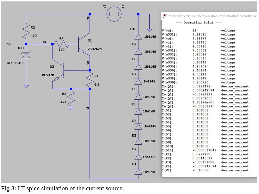
Now that the LED strip is working it could replace the CCFL. Its DC-DC converter replaces the High voltage DC-DC converter of the CCFL tapping of the same +12 [V]. But the SML03 signal generator is a complicated and high quality instrument. Bringing in a new DC-DC converter, with unknown specifications might pose a risk, it might introduce CM or DM noise ultimatly affecting the phase nosie performance. Who knows! An alternative is to use an analog regulator. It has merely to convert the +12 [V] to approx 8.56 [V] and the current is only 100 [mA]. I decided not to take a voltage regulator, but instead design a small current source. Since LED brightness is a function of current, this seemed most appropriate. In fig 3 one can see the circuit and the simulated results with LT spice. I used off the shelf components that I had anyway in stock. A few remarks on the LT spice circuit. The LED strip is simulated with ordinary diodes (1N4148), such that at 100 [mA], the voltage is about the same as measured for the LED strip. The circuit is an emitter follower. Once the current is more than Ube of Q2 divided by value of R1 (thus approx 0.7[V]/6.8 [Ω] = 103 [mA]) the Ube of Q1 is pinched off. R4 is to assure that there is no parasitic HF-oscillation of Q2. The simulated current value thru the Diodes is 101 [mA], which is what we want.
Finalizing it all
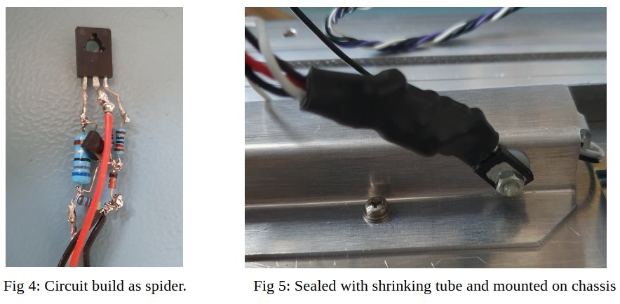
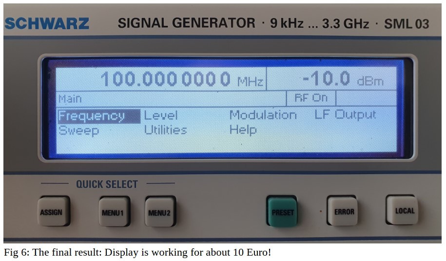
The next step is building the above circuit (fig 4). All components were from the “home-stock”. The transistor Q1 is changed to BD139. R1 is a 1W resistor, the rest ordinary components. The circuit worked as designed and the Q1 transistor did barely get any warmer. A last test was done: if switching on the instrument, that it does not introduce high voltage spikes. This was OK. With some shrinking tube it is sealed and mounted on the chassis (fig 4). The final results is shown in fig 6. SML-03 up and running!
Veuillez saisir votre adresse électronique. Les instructions de réinitialisation de votre mot de passe vous seront immédiatement envoyées par courriel.

Discussion (0 commentaire(s))