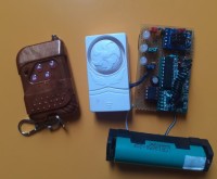
Mini alarm with radio remote control for electric bike

My son acquired a rather special electric bike... See img -> the-cycle :) It's all the rage in the area, so I suggested that we first equip it with a simple and unpretentious alarm, in order to warn it if the object moves. In the corner of a cupboard I had a few 433Mhz transmitters and receivers and a door alarm that had been given to me. These two products are easily found on the internet at low prices. I combined these products with an ATtiny85 and a tilt ball to create a remote control alarm system.
We use :
- output D3 of the radio module for detection of the alarm mode in use
D3 radio module connected to PB4, pin 3 of the ATtiny.
- output D2 of the radio module for detection of stopped alarm mode
D2 radio module connected to PB3, pin 2 of the ATtiny.
- the VT output of the radio module for confirmation of one of the two messages
VT radio module connected to PB1, pin 6 of the ATtiny
When commissioning, through PB0, pin 5 of the ATtiny, we activate a transistor which acts as power ON. (beep beep)
Originally, when activated, my door alarm emits two tones.
When turned off, no tone, hence an LED to display the status of the alarm stopped
An OFF alarm info LED indicates the alarm status. Connected to PB2, pin 7 of the ATtiny.
Code : Mini_Alarm.ino in zip
NOTA : For the tests and my ears, I replaced the alarm buzzer with an LED
I integrated the whole thing into a 4-battery carrying box, stripped of its interior partitions
Some holes were made to release the sound of the siren
The door alarm is missing its base, its batteries and the I L S contactThe base served as a template for the effector with two holes on the battery holder box in order to screw the siren into it.
The green LED is stuck at the level of the switch removed from the battery box
Two wires for the 5v power supply come out of the closed battery box once equipped with the internal ATtiny 8Mhz duly programmed with the package_damellis
The alarm is installed in the electrical trunk where the motor drivers are located.
A power supply was found there, I connected the alarm to this power supply even after the bike ignition was turned off.
I inserted an HW 083 power shield to provide 5v
The tilt has been adjusted : Contact closed -> bike position on its stand.
I will not give you precise information about the installation, this being an alarm, but I am counting on you to adapt this project to your needs.
This alarm was produced urgently with the available components. A V2 model may see the light of day....
See Mini Alarm Sleep mode
//FR
On utilise :
- la sortie D3 du module radio pour la détection du mode alarme en service
D3 module radio connecté sur PB4, pin 3 de l'ATtiny.
- la sortie D2 du module radio pour la détection du mode alarme arrétée
D2 module radio connecté sur PB3, pin 2 de l'ATtiny.
- la sortie VT du module radio pour la confirmation d'un des deux messages
VT module radio connecté sur PB1, pin 6 de l'ATtiny
Lors de la mise en service, au travers PB0, pin 5 de l'ATtiny, on active un transistor qui fait office de power ON de l'alarme de porte (beep beep)
D'origine, à la mise en service, mon alarme de porte émet deux tonalitées.
A la mise à l'arret, aucune tonalitée, d'où une led pour visualiser l'état de l'alarme arrétée
Une led info alarme OFF, indique l'état de l'alarme. Connectée sur PB2, pin 7 de l'ATtiny.
Le code : Mini_Alarm.ino est dans le zip
Pour les tests et mes oreilles, j'ai remplacé le buzzer alarme par une led
J'ai intégré l'ensemble dans un boitier porte 4 piles, dépouillé de ses cloisons intérieurs
Quelques trou ont été fait pour libérer le son de la sirène
L'alarme de porte est déséquipé de son fond, de ses accu et du contact I L S
La base à servi de gabarit pour effecteur deux perçages sur le boitier porte pile afin d'y visser la sirène.
La led verte est collée au niveau de l'interrupteur déposé du boitier porte piles
Deux fils pour l'alimentation 5v sortent du boitier porte piles refermé une fois équipé de l'ATtiny 8Mhz interne dûment programmé avec le package_damellis
L'alarme est installée dans le coffre électrique ou se trouve le drivers moteur.
Une alimentation y a été trouvée, j'ai connecté l'alarme sur cette alimentation présente même après que le contact du vélo soit mis à l'arret.
J'ai intercallé un shield alimentation HW 083 pour fournir le 5V
Le tilt a été ajusté : Contact fermé -> position vélo sur sa béquille.
Je ne vous donnerai pas d'information précise de l'installation, celle-ci étant une alarme, mais je compte sur vous pour adapter ce projet à votre besoin.
cette alarme a été réalisé dans l'urgence avec les composants disponnible. Un modèle V2 verra peut-être le jour.......
Voir mise à jour Mini Alarm Sleep mode


Mises à jour de l'auteur