Get 5-volts from an exhausted alkaline cell
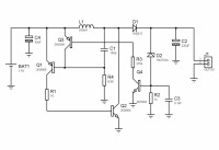
Every day we throw away usable power alkaline cells. Since the device in which we use them can not work with partially discharged cells, the circuit that I present can raise the voltage of one exhausted cell to 5V to use it in any other application, for example to turn on a led, feed a microcontroller or feed remote sensors that do not demand much energy.
Discussion (9 commentaire(s))
petrus bitbyter il y a 5 ans
petrus bitbyter
Roel Arits il y a 5 ans
So lets assume that the zener voltage is about 4V3 with a current of 1mA. Adding up the 0.7V base-emitter junction of the transistor results in an output voltage of 5V.
It is not a very precise voltage regulation, but it is good enough for most applications that require 5V+/-5%.
I've build a similar circuit like this before, and got an efficiency of around 85% out of it.
M.P.W. van de Kraats il y a 5 ans
The chemicals those things leak ususally ruin the device they are in.
Therefore, when one does try to totally exhaust batteries till the last drop, one should add some kind of leak detection as well, to prevent damage to the battery holder, and possibly other...
Johannes van Kampen il y a 5 ans
Marcel Hariga il y a 6 ans
Wer Weis il y a 5 ans
Jeden Tag werfen wir nutzbare Alkaline-Zellen weg. Da das Gerät, in dem wir sie verwenden, nicht mit teilweise entladenen Zellen arbeiten kann, kann der Schaltkreis, den ich vorstelle, die Spannung einer erschöpften Zelle auf 5 V erhöhen, um sie in jeder anderen Anwendung zu verwenden, zum Beispiel um eine LED einzuschalten, einen Mikrocontroller zu speisen oder speisen Sie entfernte Sensoren ein, die nicht viel Energie benötigen.
David Ashton il y a 6 ans
I must admit though, anything I can I convert to rechargeables.
M.P.W. van de Kraats il y a 6 ans
I would say: ain't that in the line of the Elektor projects ?
They usually ain't to usefull, if not to learn from them, get ideas by understanding new and/or different concepts.
Isaac Rose il y a 6 ans
There is a fair amount of discussion on using a 1.5v cell. But I have to wonder whether this may be a good substitute for migrating from a 3-4 cell 1.5v battery pack to using a 3.6v LiPo pack. It would be better to redesign the application circuitry to run straight from the 3.6v supply. However that may not be an option due to component selection, design resources, or due to exiting supply chain.
When I have a moment I intend to run this scenario through the simulator in Altium. In the mean time I thought I would mention it here to bring another perspective.
@David Ashton, you make a good point, in that there are COTS IC options, I know maxim semi has some ic’s which can performs the same application. The challenge becomes the return on investment for the ic. Passive components have become so cheap these days, that the cost of the ic can be 2-4 times the amount of the passive in production quantities. For a hobbyist it may be a wash, or the ic may be preferred if you don’t have an adequate stock of passives.
David Ashton il y a 6 ans
Malcolm Watts il y a 6 ans
Commenting on the circuit (which I have not analysed too closely) I would suggest that ideal active devices that should be considered for this idea range from specifically designed I.C.s for energy scavenging (high-efficiency boost converters for using wireless power which is otherwise unused) to the Zetex range of low Vce(sat) transistors which give superior efficiency to bog-standard types. I have used these in a range of projects and can attest to their excellent performance.
Malcolm Watts
KENT SWAN il y a 6 ans
Pin * efficiency = Pout
Power = I *E
(Ein * Iin) * efficiency) = (Eout * Iout)
Iin = (Eout*Iout)/(efficiency * Ein)
Assuming you wany 50ma at 5V and can convert at 90% efficiency then
Iin = (5V *0.050ma)/( .9*1.5V)
Iin = 185ma where 18.5ma is lost by the conversion circuitry
The current required to maintain the output voltage increases as the source voltage drops
Iin = 277ma (battery 1.0V)
An AA high capacity primary (non rechargable) battery typically has a capacity of lets say 2500 mah. At end of life it will have used approximately 90% of its charge and the voltage will have dropped lets say to 1.0V This means that there's approximately 250mah remaining. The low voltage switching regulator will have a minimum voltage input typically around .8 volts. We can then only extract current from 1.0V to 0.8 volts which because of internal resistance in the battery means that such an extractor is conceptually valid for normal lifetime use but is in fact a wortheless use of silicon to recover useful energy from used batteries as the runningtime will be measured in a handfull of minutes
Johannes van Kampen il y a 6 ans
KENT SWAN il y a 6 ans
Lets say that the cells are 1 volt. The rules of battery capacity say that if you stack a number of cells which have a specific capacity, then the stack will still have the same capacity but the voltage will be the sum of the voltages of each cell.
Going back to the 'debunk' response, with six cells we would have a battery with 250mah at 6V. With the input and output voltages being roughly the same then the 250mah would become availible. This means that, at 50ma draw you would get roughly 4 hours from the reclaimed stack. If you started with 6 new cells the buck-boost would be in buck mode for most of the stack's life but as it switched to boost mode, the difference in input to output would allow you to get the most out of the batteries.
The net of this discussion is that it's best to match the battery voltage with the use voltage and that buck is preferred (eg input voltage > output voltage).
Peter Williams il y a 6 ans
M.P.W. van de Kraats il y a 6 ans
However, mentioned circuitry is most likely to please the cheapgoat, that tries to save at each and every corner.
Not quite the type of public that is likely to buy Duracell.....
M.P.W. van de Kraats il y a 6 ans
However, what jumps to mind when reading this, is the image of batteries that start leaking because of being left in a device for too long.
When using such a circuitry, we should be carefull not to squeeze out the chemicals together with the last drop of energy......
Need for an additional leackage sensor ??
petrus bitbyter il y a 9 ans
I did not analyse your circuit in detail but a quick scan make me doubt it will work. An almost empty 1.5V battery will not provide much energy anymore and I expect that all it can provide will be consumed by the circuit itself, leaving nothing for the load. Nevertheless, if you want to be sure why not building the circuit. Cannot be that difficult, can it?
Your idea is not brand new. If you like to read more about this idea, google for 'joule thief'.
BTW were did you find this circuit?
petrus bitbyter
purple-bobby il y a 6 ans
Assume cell is giving 0.8V at 20uA or 600uA or 20mA. V_BE is 0.65V and transistor gain is 30. V_CE(sat) is 0.25V
At switch on there is 0.15V = (0.8V - 0.65V) across R4 and the base current of Q1 -22uA; its collector current is -660uA.
Q2 base current is 660uA and its collector current up to 20mA, however the conduction path is initially through C1 and Q1, providing positive feedback. C1 will charge up to 0.15V which is 22.5pC at 22.5mA it lasts 1ns.
There is a brief spike in current through Q2 before returning to ~20mA.
The inductor current will increase while there is a voltage across it. The voltage is 0.55V = (0.8V - 0.25V), it will reach 20mA in 9ms.
I cannot see a mechanism to switch Q2 off and force the 20mA inductor current through D1 and charge up C2. If Q2 does switch off the rise in voltage accros Q2 will discharge C1 and switch Q1 then Q2 off. However to me, it seems L1 takes too long to get going. In the 1ns while C1 charges, the current in L1 reaches 1.6uA, the gain of Q1 times Q2 would be less than 0.1.
David Ashton il y a 6 ans
https://www.ledsales.com.au/pdf/zxsc380.pdf
Florian Menke il y a 6 ans
petrus bitbyter il y a 9 ans
genuensis il y a 9 ans
Juan.Canton il y a 9 ans
petrus bitbyter il y a 9 ans
Juan.Canton il y a 9 ans