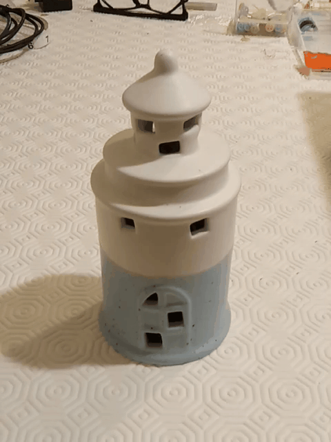
Flashing lighthouse thermometer

Repurpose an old ornament with an Arduino and an addressable LED.
We bought a ceramic lighthouse ornament at a garden centre it lit up with an led. However being powered by 2 AG13 1.5v batteries with a white led with no current limiting resistor, the illumination didn't last long. I didn't want to have to keep replacing batteries and remembering to turn if off after going to the trouble of picking it up and turning it on, a less bothersome way was needed to to make it more interesting.
I remembered that I had read somewhere that the Arduino (ATmega328) had an internal temperature sensor and I already knew that it could be powered down to prolong battery life. I thought I would use a neopixel addressable LED to flash a colour appropriate to the temperature for some milliseconds then shut down the Arduino to save the battery. This way it requires no attention, should remain active for some time, and only require battery replacement occasionally.
So using the code to access the temperature sensor I could get a value for the temperature inside the Arduino without any additional components. The accuracy of this reading is questionable without calibration but good enough for this purpose. As the Arduino was going to spend more time powered down than up I am not concerned about any heat from the CPU.
I chose to use a cheap Arduino Mini as it does not have a USB chip that would use power. Also I removed the red 'power on' led (and its resistor but that was collateral damage). I powered the Arduino via the vcc connection so that the regulator chip is not involved. The power was coming from a lipo battery which is only around 3.7 volts but by choosing to run the ATMEGA328 at 8 MHz it can run on 3.3V. As these chips can run off 5 volts I think that little extra is OK and even the neopixel illuminates at this voltage.
The sensor value is read and the colour values are chosen in a series of if the else statements. The colours used to represent the temperatures were approximated from the colours used on the tv weather forecasts, and could be refined - colour is not my best sense. The LED is turned on for 100 milliseconds then off. I used the Adafruit_sleepyDog library to put the board into sleep mode for the maximum time. The watchdog timer will restart it in 8 seconds.
After I completed this I realised I could have used a simple RGB LED instead of a Neopixel. I tried to measure the current used by the board, but I found this difficult to do. A multimeter can't read the pulse from the LED and an ocsilloscope set to see the pulse dosen't see much of the sleep current (obviously I'm reading the voltage over a shunt resistor). So I did both, an oscilloscope for the pulse and overall cycle length and the mutimeter for the sleep current. when all added together - the result was verified in time; the 1200 mAh battery had to be recharged after 90 days, so that was around 500uA.


Discussion (0 commentaire(s))