
ESP-FLY: The Smallest ESP32 Drone You Can Build!
Build the ESP-FLY, a tiny, phone-controlled ESP32 pocket drone powerful enough to fly indoors & outdoors!
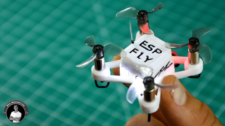
Meet the ESP-FLY, a micro quadcopter built around an ESP32 board, a custom PCB, and lightweight 3D-printed or DIY PVC frame. The perfect weekend project to build purely for fun and geared for the intermediate or advanced maker with prior experience using drones and making microcontroller-based projects.
This guide will walk you through everything from my design process, the assembly, programming, to flying - so you can build your own ESP-FLY from scratch and have fun flying this tiny beast almost anywhere. Let’s dive in!
1. Gathering Parts and Resources
This guide will walk you through everything from my design process, the assembly, programming, to flying - so you can build your own ESP-FLY from scratch and have fun flying this tiny beast almost anywhere. Let’s dive in!
1. Gathering Parts and Resources
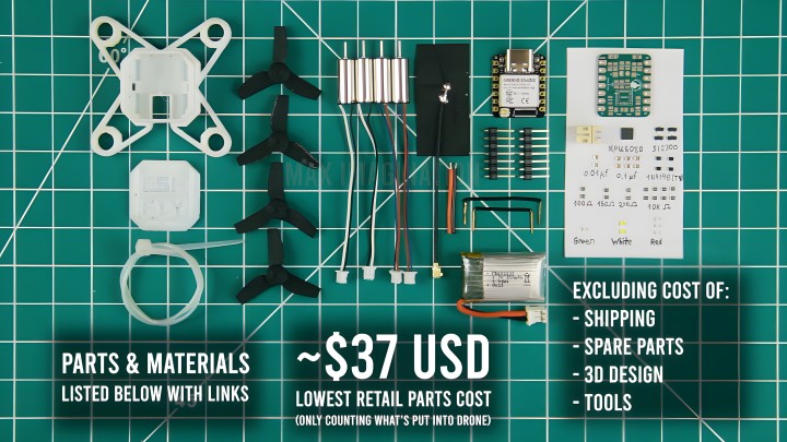
To bring the ESP-FLY to life, you’ll need a lightweight frame, coreless motors, a custom PCB, an ESP32-S3 microcontroller, an inertial measurement unit (IMU), MOSFETs for the motor driver, and more.
Here’s the full parts list with links:
- (x1) Seeed Studio XIAO ESP32-S3 - 10% OFF | Code: MaxImagination (valid until April 12):
- On Seeed Studio Official Website: https://www.seeedstudio.com/XIAO-ESP32S3-p-5627.html?utm_source=youtube&utm_medium=MaxImagination&utm_campaign=ESP32drone ($7.49)
- On Amazon: https://amzn.to/4byrbve
- On AliExpress: https://s.click.aliexpress.com/e/_ok4s5cv
- (x1) MPU6050 IC - https://amzn.to/4gJoGY1 ($4.40)
- (x4) SI2300 N-MOSFET - https://amzn.to/42XAFhq ($0.55)
- (x4) 1N4148 Switching Diode - https://amzn.to/4k2RDBa ($0.08)
- Resistors - 0805 SMD (From Kit): https://amzn.to/3X3Mi2l ($0.10)
- (x9) 10KΩ
- (x2) 200Ω
- (x2) 150Ω
- (x2) 100Ω
- Capacitors - 0805 SMD (From Kit): https://amzn.to/41i0lUJ ($0.09)
- (x6) 0.1μF
- (x2) 0.01μF
- LEDs - 0805 SMD (From Kit): https://amzn.to/41zA9nl ($0.30)
- (x3) Red
- (x2) White
- (x1) Green
- (x1) 90° JST Power Connector - https://amzn.to/3X06ges
- ($0.18) (x4) Micro Coreless Motors - https://amzn.to/3EDFUZD ($10.99)
- (x1) 150-250mAh LiPo Battery - https://amzn.to/4bS8YZB / https://www.seeedstudio.com/Crazyflie-Nano-Quadcopter-Spare-battery-BC-BL-01-p-1362.html ($9.99 avg)
- (x4) Propeller - https://amzn.to/4i0U0Ct ($2.50)
- (x1) Small Zip-tie - https://amzn.to/4gMhQRv ($0.04)
- Solid core jumper wires - https://amzn.to/41PWBtG ($0.10)
- 4g of 3D printed filament for frame/enclosure - https://amzn.to/4izYf8l ($0.07)
- (x1 of 5) PCB made by JLCPCB - ($0.42) https://jlcpcb.com/?from=MaxImagination
Total cost of the above parts excluding cost of shipping, spare parts, 3D model, and tools you may need: $37.30 USD (+- $10)
It’s the lowest retail parts cost - only counting what is put into the drone.
EXTRA:
Obtain these if you want FPV video:
- WT07 Micro 5.8GHz 25mW Camera with VTX - https://amzn.to/4hUpZF3 ($25.99)
- FPV Headset - https://amzn.to/4kR8WVY
Project Resources:
- Project Files (Firmware, Gerber, Schematic, and more): https://drive.google.com/drive/folders/18QSSe5u8A_p2iix2rqLfaRU-QODWJp0w?usp=sharing
- Drone Frame 3D design/model (STL files) - https://cults3d.com/en/3d-model/gadget/esp-fly-an-esp32-micro-drone-body-frame-3d-design-stl-files
- Software - ESP-IDF (Download Offline Installer “5.0.7.” 0.96 GB): https://dl.espressif.com/dl/esp-idf/?idf=4.4
- ESP-Drone Mobile Control App: https://www.pgyer.com/a27L?sign&auSign&code
- Open-source Firmware from Circuit Digest - ESP-Drone: https://github.com/Circuit-Digest/ESP-Drone (Instead use the firmware from my folder link above for ease of setup)
Credits to JobitJoseph from Circuit Digest for firmware - https://www.youtube.com/watch?v=uzZjk0TQKtU&t=11s
Thanks to fellow maker - Dr Electronics for helping me get the firmware working! https://www.youtube.com/watch?v=TanPR1QwJeU&t=477s
Thanks to fellow maker - Dr Electronics for helping me get the firmware working! https://www.youtube.com/watch?v=TanPR1QwJeU&t=477s
To learn more about ESP-Drone from Espressif:
- Documentation: https://docs.espressif.com/projects/espressif-esp-drone/en/latest/gettingstarted.html
- Hardware Reference: https://docs.espressif.com/projects/espressif-esp-drone/en/latest/hardware.html
- Flight Control System: https://docs.espressif.com/projects/espressif-esp-drone/en/latest/system.html
Refer back to the above info as you follow along to the blog. Let’s get started!
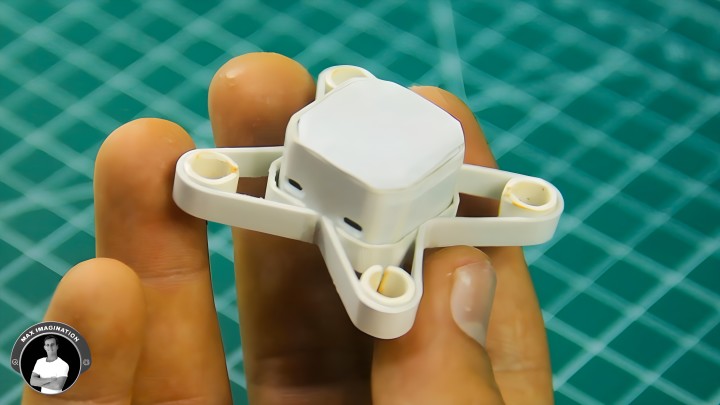
2. Designing the Drone Frame
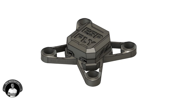
Using my go-to CAD software - Autodesk Fusion, I modeled the 50mm quadcopter frame with basic aerodynamics in mind.
The design features a closed body, two-prong motor arms, and an engraved top cover with an optional cover containing an FPV camera mount for first-person-view flying.
Purchase the STL files from Cults 3D and use the recommended 3D print settings listed there: https://cults3d.com/en/3d-model/gadget/esp-fly-an-esp32-micro-drone-body-frame-3d-design-stl-files
3. 3D Printing the Frame
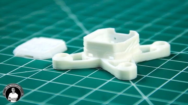
While the printer heats up, import the three parts into your slicer, position them, and apply the recommended print settings:
Layer Height: 0.12mm
Infill Density: 10%
Support: Yes
Speed: 100mm/s
Nozzle Temp: 220°
Build Plate/Bed Temp: 60°
Cooling: Yes
Infill Density: 10%
Support: Yes
Speed: 100mm/s
Nozzle Temp: 220°
Build Plate/Bed Temp: 60°
Cooling: Yes
Additional info:
Print Material: ePLA (1.75 mm):https://amzn.to/4izYf8l
PLA material cost (~5g) : $0.1 USD
3D printed parts weight: ~5g including alternate covers
PLA material cost (~5g) : $0.1 USD
3D printed parts weight: ~5g including alternate covers
I used an Elegoo Neptune 4 Plus for its speed and high-quality prints - completing the frame in just 30 minutes!
4. DIY PVC Frame Alternative
No 3D printer? No problem! You have the option to make the PVC version of the drone frame. Print the PVC frame A4 blueprint, heat 2-inch (1-2mm & length 200mm) PVC pipe to flatten into a sheet, stick the sheet of paper onto the PVC sheet, cut out the pieces with a rotary tool or hobby knife and drill holes where necessary
Once peeled from paper, sand the parts to the point they're less than a millimeter in thickness for weight management.
Start forming the frame by bending 4 motor holders, frame head, inner frame, and outer frame pieces according to the outlines on the blueprint sheet. With all bent accordingly, you can begin supergluing the parts together.
For the frame head to fit in, 3 corners poking inward will need to be trimmed off. Also glue some pieces of PVC on the inside to prop-up the boards. Then assemble the top cover.
With that, you go from 11 grams of flat PVC into a complete DIY drone frame weighing just 6 grams. The drone will still fly if assembled with the PVC frame despite being 2 grams heavier. However, I will go with building my drone on the 4-gram 3D printed frame for its detailed and highly-accurate design.
5. Designing & Ordering the PCB
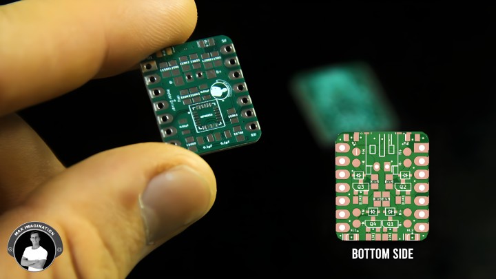
Using Flux PCB design software, I integrated the motion sensor, motor drivers, and LED indicators into a compact 4-layer PCB. Upload the Gerber file to JLCPCB and select your board specs:
Set the layers to 4, choose your desired quantity, select 1.2mm thickness, and pick a board color - green is the fastest and most cost-effective option. Don’t forget to select "Remove Mark", and that’s it! Add it to your cart, choose shipping and payment options, and place your order - it’s as simple as online shopping. JLCPCB offers high-quality PCBs as low as $2! https://jlcpcb.com/?from=MaxImagination
6. PCB Assembly - Soldering Components
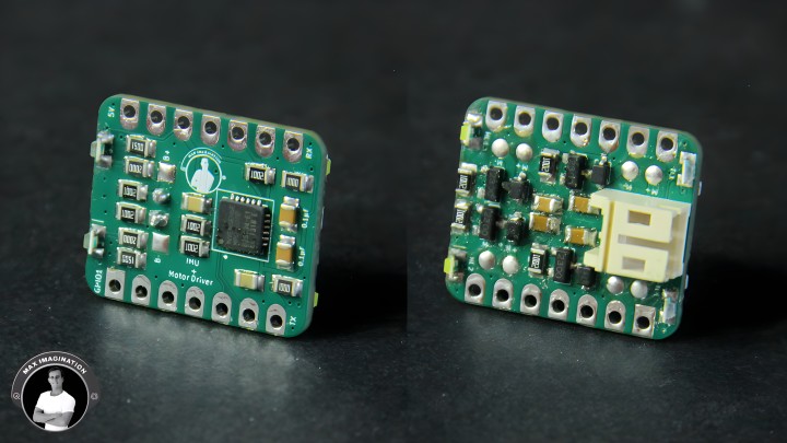
Using an SMD stencil ordered along with the PCBs, apply solder paste to one side of the PCB, then place resistors, capacitors, indicator LEDs, and the MPU6050 IMU for the top side which is reflow soldered using a hot plate. For the motor driver side, add some solder paste to those pads, hand-solder the components such as the resistors, diodes, capacitors, MOSFETs, and JST battery connector.
When it comes to placing the MPU6050 motion tracking IC, it’s crucial you align the dot on the chip with the dot on the PCB for correct orientation. The chip and other SMD components can be bought in tape reels or salvaged from modules and other boards.
With the IMU or Inertial Measurement Unit + motor driver module complete, it weighs only one gram (1g)!
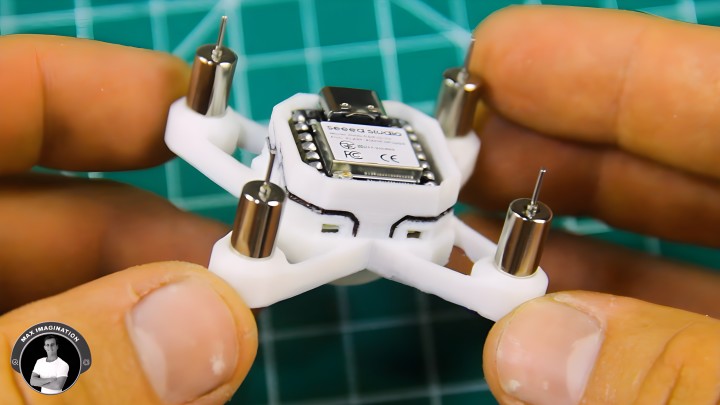
7. Installing the ESP32 Flight Controller
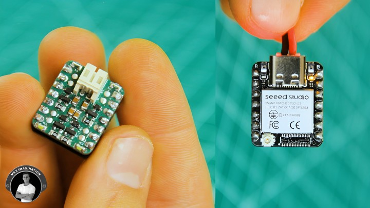
Now that the IMU/motor driver module is assembled, it’s time to give the quadcopter its brain.
Seeed Studio’s XIAO ESP32-S3: https://www.seeedstudio.com/XIAO-ESP32S3-p-5627.html?utm_source=youtube&utm_medium=MaxImagination&utm_campaign=ESP32drone
Mount the microcontroller onto the custom module with orientation in mind using short wires to bridge battery lines and pin headers for connecting the board’s pins. This tiny yet powerful board handles low-latency (7-25ms), WiFi-based control and direct battery charging via USB-C, making it perfect for micro drones.
8. Main Assembly
8. Main Assembly
To make it stand out, you may color the debossed areas with a pen such as the drone’s name, decorative details, and branding.
Secure the flight controller inside the frame, add a zip-tie battery strap, and insert the 6x15mm coreless motors into the arms. When you buy these motors, check you get two clockwise (CW) and two counter-clockwise (CCW) motors which can be told apart by wire color. This is crucial because each motor needs to rotate in a specific direction, requiring some to have reversed brushes to ensure proper operation and minimize wear.
Route and solder the motor wires, ensuring the correct CW and CCW motor order:
- Front Right = CCW (Black & White wires)
- Rear Right = CW (Blue & Red wires)
- Rear Left = CCW (Black & White wires)
- Front Left = CW (Blue & Red wires)
9. Adding Landing Gear & Antenna
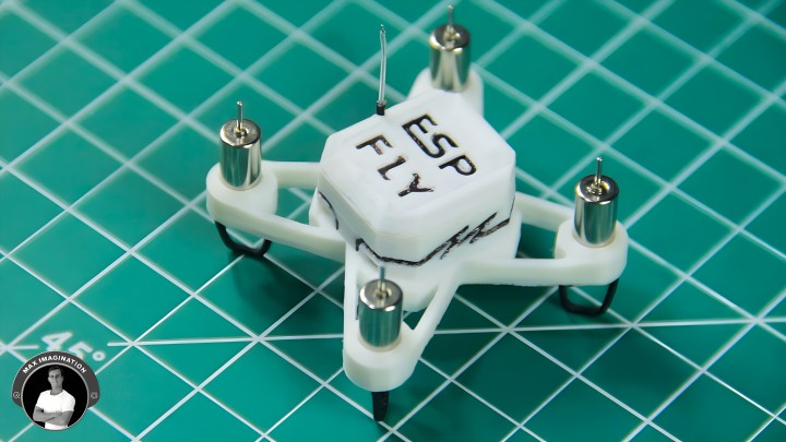
For legs (landing gear), bend four 25mm solid-core jumper wires into V-shapes and insert them into the holes in the motor mounts.
Modify the microcontroller’s included antenna by removing the flex PCB and trimming the shielded portion, then route it under the drone’s cover for a 100m control range.
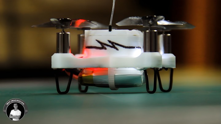
10. Installing Propellers & Battery
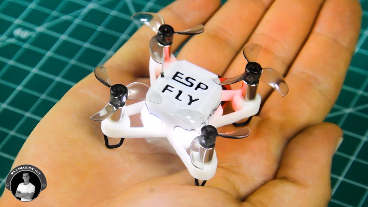
Use GEMFAN tri-blade props for 0.8mm shafts, ensuring the correct spin direction. Any other 30mm Bi, Tri, Quad, or more bladed propellers with a 0.8mm shaft diameter will work.
The motors shall spin the props inward in relation to the front and rear of the drone and be able to produce downward thrust. Be careful when attaching these so that the rotor does not pop through the motor bottom part. Replacing these propellers can be easily done with the included prop-removal tool. To easily differentiate the drone’s front and rear side when in the air, I suggest using different colored props for the rear motors.
For the battery, a 150-450mAh (Recommended) LiPo with at least 25C discharge rate will work. I am using a 250mAh LiPo with a 30C discharge rate - it’s the perfect size. Charging can be done via USB-C or a multi-charger.
11. Flashing the ESP-Drone Firmware
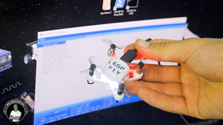
Now, it's time to flash the firmware onto the drone using ESP-IDF, the official development framework for ESP32 chips. The ESP-Drone firmware and project, originally developed by Espressif, was inspired by BitCraze’s Crazyflie - a micro drone with a lot more sensors commonly used in swarm coordination. For technical details, refer to Espressif’s documentation: https://docs.espressif.com/projects/espressif-esp-drone/en/latest/gettingstarted.html
A big thanks to Circuit Digest and Jobit Joseph for their modified version of ESP-Drone firmware, which helped make this project more accessible. Also, shoutout to DR Electronics for assisting with the software setup. I've linked their channels in the project resources section.
To Flash the Firmware:
- Download ESP-IDF 5.0.7 (Found in project resources, ~0.96GB).
- Run the installer and select PowerShell & ESP32S3 board support when prompted.
- Download the firmware (use my pre-configured firmware files for the ESP-FLY).
- Extract the firmware, navigate to the esp-drone folder, and copy its directory path.
- Open ESP-IDF PowerShell, type “cd “ with the space, then paste the folder path and press Enter.
- Type “idf.py -p COMX flash monitor” (replace COMX with your actual port, found in Device Manager).
If everything is set up correctly, you’ll see "Ready to Fly" in the output log. If you spot sensor, CPU, or driver warnings, don’t worry - these components aren’t used in this build. Just ensure the motion sensor is detected and the WiFi access point is active.
To Customize the Firmware Settings:
- Type “idf.py menuconfig” in PowerShell.
- Navigate through the ESPDrone Config menu.
- Adjust pins, sensors, LEDs, and motor assignments if needed.
- Save changes, then reflash the firmware.
For advanced tuning, use the Crazyflie Client:
- Type “cfclient” in PowerShell to open the interface.
- Connect your PC to the drone’s WiFi AP (password: 12345678).
- Configure joystick mapping and select the UDP address.
- View real-time battery voltage, motion tracking, pitch, roll, and yaw data.
- Adjust trim, rates, thrust limits, and flight behavior.
Now, your ESP-FLY is almost fully configured and ready to be flown!
12. Installing App & Configuring Drone Controls
12. Installing App & Configuring Drone Controls
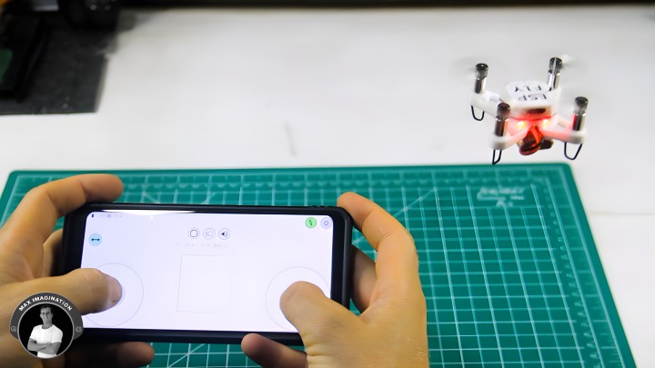
To control the drone, you’ll use your phone. Follow these steps:
- Download the ESP-Drone app:
- iOS users: Find it on the App Store.
- Android users: Use this link: https://www.pgyer.com/a27L?sign&auSign&code, download the APK, and allow "Install Unknown Apps" in phone settings.
- Power on the drone and place it on a flat surface for calibration (motors will briefly spin to confirm success).
- On your phone, go to WiFi settings and connect to the drone’s access point (Password: 12345678).
- Open the app and tap the connect button - the drone’s green LED should light up, confirming a successful connection.
Optimizing Flight Controls:
Before flying, tweak these settings in the app for better stability and control:
Before flying, tweak these settings in the app for better stability and control:
- Adjust joystick mode, Pitch/Roll trim to stabilize flight.
- Enable Advanced Mode for increased angles and thrust values.
- Select control type: Use either on-screen joysticks or tilt-to-control.
- Customize joystick size for comfort.
- Keep the Yaw Lock button enabled to maintain full maneuverability.
Mastering Drone Controls:
If you're new to flying drones, here’s how it works:
- Left joystick (Throttle & Yaw): Move up to increase power, left/right to rotate.
- Right joystick (Pitch & Roll): Move in any direction - forward, backward, left, or right.
Once set up, you’re ready to fly the ESP-FLY!
13. Flight Test & Performance
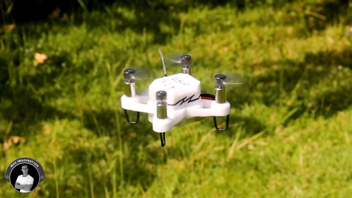
Throttle up and get airborne! The ESP-FLY has a 2.7:1 thrust-to-weight ratio (68g over 25g), enabling smooth, stable flight even in moderate wind conditions and lasts 5 ½ minutes in the air with a 250mAh battery. I took mine up to 50 meters before losing sight - so the range is more than enough!
Another element complimenting its performance is its weight of 18g alone and 25g (grams) with the battery, the ESP-FLY is lighter than my 2024 Mini Arduino FPV drone. Its thrust-to-weight ratio ensures agile flight, while WiFi control removes the need for a dedicated transmitter like on my Arduino drone.
14. Adding an FPV Camera
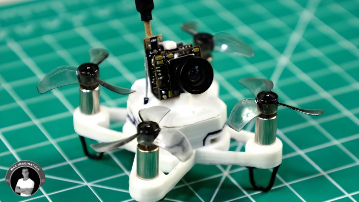
For immersive FPV flying, install a WT07 3g micro FPV camera with the extra 3D-printed camera mount cover. Wire it directly to the battery connector at the bottom of the board, then bind it to FPV goggles using an auto-search. The 100m+ video range makes it perfect for indoor and outdoor flights!
15. Customizing & Upgrading Tips
The ESP-FLY is highly customizable, with firmware support for additional features. Here are some upgrades you can consider:
- Active Buzzer: Replace the battery warning LED with a small buzzer for an audible low-battery alert.
- FPV Camera: Add a WT07 micro FPV camera for first-person view flying or OV2640-style camera connected to microcontroller (when firmware gets an update to support one).
- Larger Battery: Upgrade to a higher capacity 300-450mAh LiPo for longer flight times.
- Improved Antenna: Swap out the short, modified WiFi antenna for a high-gain external antenna to extend control range.
- Custom Tuning: Adjust flight parameters in the Crazyflie Client for better handling.
- Alternative Motors & Propellers: Experiment with different coreless motors and prop sizes to optimize performance.
- RGB LEDs: Add addressable LEDs for custom lighting effects during flight.
All of these modifications can be implemented within the existing firmware, making the ESP-FLY even more capable.
16. Ready to Build Your ESP-FLY?
This DIY ESP32-powered drone combines performance, affordability, and customization. Whether you go 3D-printed or PVC, add an FPV camera, or tweak the firmware, ESP-FLY is an exciting maker’s project to take on over a weekend.
Everything you need from PCB files, 3D prints, firmware, and components - is linked at the top of this blog. Get building and share how cool your ESP32 micro drone turns out with the maker community! Looking forward to seeing your ESP-FLY in the sky! Watch the full build process, flight tests, and more by clicking on the ESP-FLY’s video below.
Discussion (3 commentaire(s))