
Electronic load for DC and AC
In this project I show you an electronic load for DC and AC
This Electronic Load for DC and AC has some remarkable Features:
Input voltage up to 400V
Load current up to 10A
Power dissipation up to 200W
Remote controllable via (isolated USB interface)
Suitable for DC and AC
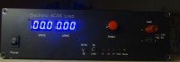
7-segment displays for VRMS and ARMS
After publishing this project in Elektor issue Sept./Okt. 2021
you can find the (updated) documents in the attachments.
Input voltage up to 400V
Load current up to 10A
Power dissipation up to 200W
Remote controllable via (isolated USB interface)
Suitable for DC and AC
7-segment displays for VRMS and ARMS
After publishing this project in Elektor issue Sept./Okt. 2021
you can find the (updated) documents in the attachments.
Mises à jour de l'auteur