
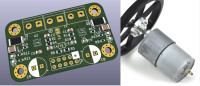
DUAL Motor brushed DC PWM Driver Arduino (H bridge 4A/24V) #eduino.io
Every robot project needs at least a motor driver, you want your MCU to make something move right? MP6619 evaluation!
Are you tired of boring MCU projects with nothing but a simple blinky LED? Do you want to actually make something move with your MCU? Then listen up, because every robot project needs a motor driver. But don't waste your time browsing Chinese sites for a solution, because the lack of documentation and schematics will leave you lost in the forest. And even if you do find something, the sizing is often strange and heatsinks are required, making integration into your project a headache.
We know this problem and solved it using the MP6619 from MPS,
That's why this project is also the solution for you.
* Controlling 2 motors in speed with PWM
* brakes
* freewheel
* short circuit protection (SCP)
* Current limiting (OCP)
* Overvoltage protection (OVP)
* suitable for a reasonably large power (around 100 Watt).
* Usable from 6 Volt up to 28 Volt
If you like a little more voltage in your life, goes in over voltage protection (OVP) at 32 Volts.
You can connect your MCU one directly to this, 3.3 Volt or 5 Volt compatible.
What more could you want? Really (let me know)
Often you want to get started quickly and don't have time to make a study of all the options, so you choose this driver.
The driver detects short circuit, overheating and gives a signal back to your MCU, it contains 2 H bridges from efficient N-channel mosfets.
The Rds (on) is 65 mOhm (which is pretty low, so good)
By default, the output current is limited to 4 Ampere.
You can increase this to 5 Ampere by replacing a resistor.
Are you tired of using clunky, outdated drivers that your grandfather would have used?
Say goodbye to the past and welcome the future with our super-compact motor driver! At just 29x49 mm with mounting holes at a normal grid, this driver is modern and sleek.
And the best part?
No heatsinks needed!
But be warned, connecting the logic-pins to a high voltage power supply will result in destruction - as we have proven experimentally by burning one to a crisp.
So why settle for antique technology when you can upgrade to our state-of-the-art motor driver?
-- Nederlandse tekst
Ieder robot project heeft minimaal een motor driver nodig, je wil met je Microcontroller iets laten bewegen toch?
Een knipper-LED wordt gauw erg saai.
Je wilt het wiel niet uitvinden, online zie je door de bomen geen bos meer op de Chinese sites.
Zaken die je ziet in online shops missen documentatie en schema's over hoe het werkt.
De maatvoering is vaak vreemd, koelplaten zijn vaak nodig, integratie in je project is lastig.
We kennen dit probleem en losten het op.
Daarom is dit project ook de oplossing voor jou.
* 2 motoren in snelheid sturen met PWM
* remmen
* vrijloop
* kortsluitveilig (SCP)
* stroombegrensd (OCP)
* overspanningsbeveiliging (OVP)
* geschikt voor een redelijk groot vermogen (rond 100 Watt).
* bruikbaar vanaf 6 Volt tot 28 Volt
Als je graag wat meer spanning in je leven wil, gaat in over voltage bescherming (OVP) bij 32 Volt.
Je kan hier je MCU direct een aan koppelen, 3.3 Volt of 5 Volt compatible.
Wat wil je nog meer? Echt? (laat het me weten)
Vaak wil je snel aan de slag en heb je geen tijd om een studie te maken van alle opties, daarom kies je dus voor deze driver.
De driver detecteert kortsluiting, oververhitting en geeft een signaal terug aan je MCU, het bevat 2 H bruggen uit efficiente N-channel mosfets.
De Rds (on) is 65 mOhm (en dat is behoorlijk laag, dus goed)
Standaard wordt de uitgangsstroom begrensd tot 4 Ampere.
Je kan dit verhogen tot 5 Ampere door vervangen van een weerstandje.
De afmetingen zijn super-compact, namelijk 29x49 mm en de montagegaten zitten op 40x25 mm (gewoon een normaal grid)
Geen koelpaten nodig.
Moderne technologie, geen antieke drivers zoals je opa die al gebruikte.
De logische niveau's op de ingang moet je begrenzen tot 5 Volt, dus 3V3 of 5Volt is prima, maar verbinden met de 12 Volt levert rook/vuur en stank. Dat is nu bewezen in de praktijk ;-)
Mises à jour de l'auteur