
Basement ventilation system - control unit [140432]
This is the second part of our version of the project presented in the original posting from Tueftler, see http://www.elektor-labs.com/project/feuchtegesteuerte-kellerl-ftung-humidity-basement-ventilation-140154.13770.html.
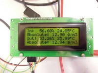
This is the second part of our version of the project presented in the original posting from Tueftler, see http://www.elektor-labs.com/project/feuchtegesteuerte-kellerl-ftung-humidity-basement-ventilation-140154.13770.html. The main reason for redesigning the complete project is that we designed lots of PCB’s with a microcontroller, LCD and switches before, and that our Platino board was already designed to be a universal (Arduino) board for many applications. We presented the CC2A humidity/temperature BoB earlier (http://www.elektor-labs.com/project/cc2a-humidity-sensor-bob-140154.14269.html), as a replacement for the more expensive HYT-939 used in the original project. In this design we will build the central control unit for the ventilation system. The Platino board will read relative humidity and temperature values form two CC2A BoB’s. It calculates the absolute humidity (in g/m3) inside and outside, and provides logic signals for opening/closing a window and switching a fan on/off to keep the humidity in the basement as low as possible. The power drivers for controlling the window (motor + gear) and the fan will follow later. Tueftler uses the following criteria for the system:
- H²O in g/m³ inside < outside , fan off & window closed
- H²O in g/m³ inside > outside , fan on & window open
- error in measurement (e.g. sensor missing): fan off & window open
- relative humidity inside < 65%: fan off (save power) & window open
- Temperature inside < 3°C : fan off & window closed (frost protection)
Since the measurements are taken every 10 minutes (except in situations where the values appear to be faulty, like when a sensor is missing), it’s not really necessary to add hysteresis to the system. But maybe it's a good idea to make some of the parameters/thresholds in the system adjustable, like the temperature threshold for activating frost protection. Ideas, suggestions and comments are appreciated…
Discussion (3 commentaire(s))