Automatic Night Lamp Circuit
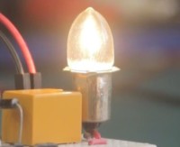
Welcome to our Automatic Night Lamp Circuit project! This innovative circuit is designed to intelligently sense ambient light levels and automatically switch on a lamp when it gets dark.
This content is also available at Max Imagination’s Workshop.
Welcome to our Automatic Night Lamp Circuit project! This innovative circuit is designed to intelligently sense ambient light levels and automatically switch on a lamp when it gets dark.
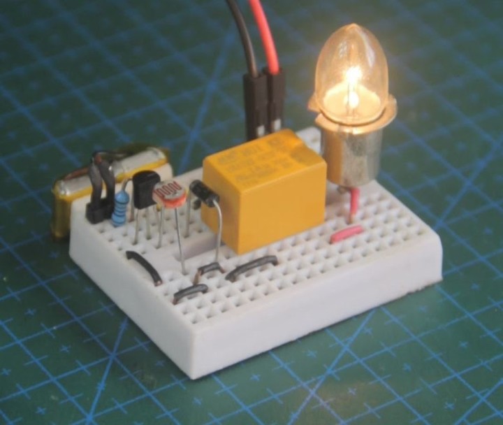
Purchase links to parts used in this circuit can be found below.
Parts and modules required
- (x1) LDR: https://amzn.to/4bXFPfq
- (x1) Transistor (2N2222): https://amzn.to/3UZkfRz
- (x1) 1KΩ Resistor: https://amzn.to/3wJSrGD
- (x1) Diode: https://amzn.to/48y6Pix
- (x1) Relay (5V DC coil | 250V AC switch): https://amzn.to/4c7D4Z4
- (x1) Light Bulb: https://amzn.to/3SVm2o9
- (x1) 3.7V LiPo Battery: https://amzn.to/3IgIdAn
- (x1) Jumper Wires: https://amzn.to/3IgZSHQ
- (x1) Mini Breadboard: https://amzn.to/3uJsVB1
Overview
This circuit utilizes components like light-dependent resistors (LDRs) and transistors to detect changes in light intensity. When the surrounding light diminishes to a certain level, the resistance of the LDR increases, triggering the transistor to conduct and turn on the lamp.
Our detailed explanation will walk you through each component's function, providing a step-by-step guide on constructing this circuit yourself. Whether for home security, convenience, or energy conservation, this automatic night lamp is a practical and fun electronics project for beginners and enthusiasts alike.
Experience the magic of automation and learn the fundamentals of circuitry with our Automatic Night Lamp project today!
Schematics
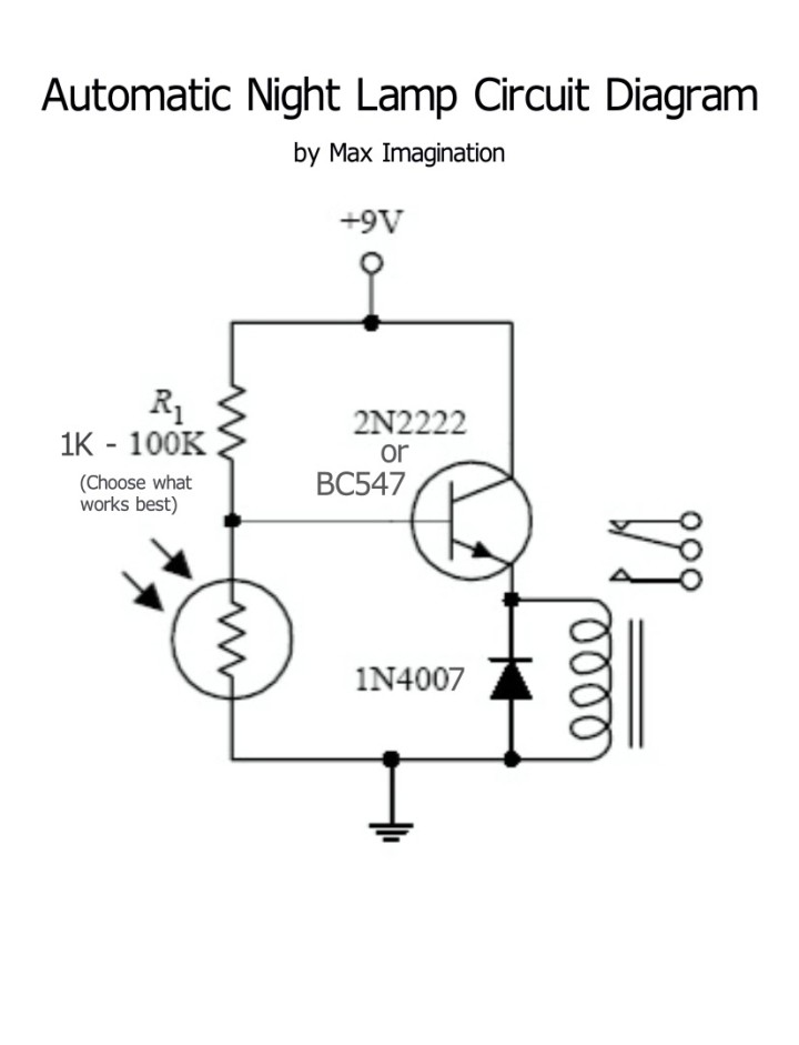
1. Voltage Divider with Light Dependent Resistor (LDR) and Resistor:
The LDR is a light-sensitive component that changes its resistance based on the amount of incident light. In conjunction with a fixed resistor (forming a voltage divider), it creates a varying voltage output that changes with ambient light levels.
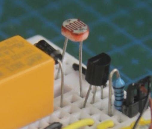
When exposed to darkness, the resistance of the LDR increases, causing the voltage across the divider to rise due to the change in resistance.
2. NPN Transistor:
The NPN transistor acts as a switch in this circuit. When a sufficient voltage is applied to its base, the current flows from the collector to the emitter.
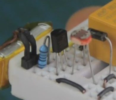
The voltage from the voltage divider (which changes with light intensity) is fed into the base of the transistor. If you do not possess a "2N2222" NPN transistor, you may use the well-known alternative - "BC547".
3. Relay:
The relay is an electromagnetic switch that uses an electromagnet to mechanically switch its contacts when activated by an electrical signal, allowing for the control of higher power appliances to be toggled on or off.
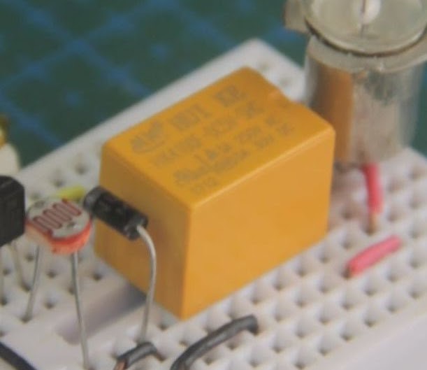
In this circuit, the relay's coil is connected to the collector of the NPN transistor. When the transistor conducts (due to low ambient light), it energizes the relay coil.
4. Incandescent Light Bulb (Connected with Relay):
The tiny incandescent light bulb is connected through the relay's contacts to its own dedicated external power source with the right voltage (3.6V) supplied to it. When the relay coil is energized (due to darkness sensed by the LDR), it closes the relay contacts, completing the circuit for the light bulb.
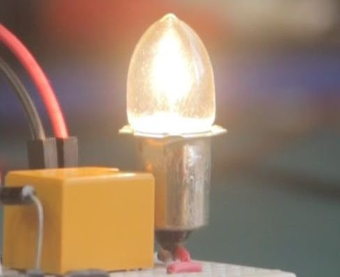
This little power-hungry light bulb was used in the circuit instead of an ordinary LED to resemble the use of automating a full-sized household light bulb which works in a similar way, with one difference being in the type of current it runs on - DC.
How the Components Work Together
During daylight or when ambient light is sufficient, the resistance of the LDR is low, causing a lower voltage at the base of the transistor. As a result, the transistor remains in a non-conductive state, and the relay coil is not energized.
However, when the ambient light decreases (for instance, in the evening or in a darkened room), the resistance of the LDR increases, causing a higher voltage at the base of the transistor.
This increased voltage allows the transistor to conduct, energizing the relay coil. As a result, the relay contacts are closed, allowing current to flow through the incandescent light bulb, which then illuminates, providing light in the dark environment.

Essentially, the circuit detects changes in ambient light levels using the LDR, uses the transistor as a switch, and employs the relay to control the connection of the light bulb, creating an automatic night lamp that turns on when it gets dark.
To see the circuit in action, check out the video below:


Discussion (0 commentaire(s))