Analogue alternating linear LED fader using 2 different approaches
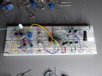
LEDs and closed loop brightness control ? Or using 'ancient' techniques such as current squaring current mirrors ? Let's go analogue for a change ....
Most of the circuits to fade a LED in or out, are digital circuits using a PWM output of a microcontroller. The brightness of the LED is controlled by changing the duty cycle of the PWM signal. Soon you discover that when linearly changing the dutycycle, the LED brighness does not change linear. The brigtness will follow a logarithmic curve, meaning that the intensity changes fast when increasing the dutycycle from 0 to lets say 70% and changes very slow when increasing the dutycycle from lets say 70% to 100%.
The exact same effect is also visible when using a constant current source and increasing the current linear f.e. by charging a capacitor with a constant current.
How come ? Well, LEDs are non-linear devices, just like other diodes and show an exponential relation between forward voltage and forward current when increasing the voltage above the forward voltage drop of the junction.
In Fig2 you can see that the brightness perception of a LED has a logarithmic curve due to the exponential voltage to current relation. When the LED just starts "conducting" the intensity increases fast with increasing current. But once "conducting", the intensity increases slow with increasing current.
To compensate for this effect, we can choose between an open loop approach or a closed loop approach :
Schematics :
The exact same effect is also visible when using a constant current source and increasing the current linear f.e. by charging a capacitor with a constant current.
How come ? Well, LEDs are non-linear devices, just like other diodes and show an exponential relation between forward voltage and forward current when increasing the voltage above the forward voltage drop of the junction.
- See Fig1 for the voltage/current relationship.
- See Fig2 for the brightness perception.
- See Fig3 for the brightness curves resulting from a linear or an exponential (kind of quadratic) changing current.
In Fig2 you can see that the brightness perception of a LED has a logarithmic curve due to the exponential voltage to current relation. When the LED just starts "conducting" the intensity increases fast with increasing current. But once "conducting", the intensity increases slow with increasing current.
To compensate for this effect, we can choose between an open loop approach or a closed loop approach :
- The closed loop approach uses an LDR to measure the LED light intensity. This signal is converted into a current using a current mirror. A linear triangular waveform is used as the source for the fader and is also converted to a current using a current mirror. The measured light current is subtracted from the triangular waveform current. The LED is fed with the resulting current, so the brightness is as linear as the linearity of the LDR.
- In the open loop approach, we need to add a quadratic or exponential growing current so the logarithmic intensity curve is flattened out. This can be done with an anti-log or exponential amplifier using an OPAMP, but i found a simpler circuit that is based on a current mirror and generates a quadratic function using 2 diodes in reference "leg" of the current mirror.
Schematics :
- Schematic1 : approach using LDR to linearise the LED brightness by feeding back the brightness that is converted to a voltage by an LDR. This requires an extra LED to be put in series with the LED that we want to control.
- Schematic2 : approach using a current squaring circuit to linearise the LED brightness by compensating the logaritmic brightness curve with a quadratic function.
- Schematic3 : Combining the 2 approaches leads to a linear alternating LED fader.
Mises à jour de l'auteur
Roel Arits il y a 7 ans
That statement is not correct :
The only reason for the non-linear brightness perception of the LED, even when feeding the LED with a constant current, is the logarithmic perception of the human eye. Just like the other human senses, also the eye has a logarithmic brightness perception.
My confusion started when i used an LDR (in the closed loop approach) to linearize the brightness of the LED. I always thought that LDR's have a linear resistance versus light intensity graph. But when taking a closer look in the LDR (cadmium sulphide) cell specifications, i discovered that the linear resistance change was in fact drawn on a logarithmic scale. So LDR's are not linear at all, but logarithmic.
Furthermore, the logarthmic resistance curve of an LDR seems to match the logaritmic brightness perception of the human eye pretty close. That is why the LDR does the job so well. Never too old to learn i guess. :-)
When the LDR is used as part of a voltage divider, together with a fixed resistor, this will cause an extra non-linear effect. This effect is because in that kind of voltage divider, not only the voltage over the fixed resistor changes, but also the current.
For more info about non-linear voltage dividers :
https://www.maximintegrated.com/en/app-notes/index.mvp/id/838
Arnoldus il y a 7 ans
I wonder if a tangent oscillator exists.... and if it can be used as logarithmic signal..... :-o
Roel Arits il y a 7 ans
When you phase shift a sine wave 90 degrees, you get a cosine wave. When you use an analog divider to divide the sine wave by the cosine wave, you should get a tangential
wave.
Hm, i have to add that to the list of things to play with.
Thanks Arnoldus. :-)
Arnoldus il y a 7 ans
And the signal has to be rectified to get a positive signal only. See pictures.
And then drive a LED with a voltage to current converter...?
Ask Clemens to start a new competition to build a tangential oscillator? :-)
rectfied tangens (9kb)
Roel Arits il y a 7 ans
I like this kind of brainstorming because it can lead to totally new ideas and circuits.
I think Clemens is now trying to find a tangential oscillator for us in all the Elektor 300, 301, 302, 303, 305, 309, 311 circuits books. :-)
ClemensValens il y a 7 ans
I did some Excel (see attachement). On the left the tangent is rectified but the jump from +infinity to minus infinity has been left out, resulting in a nice top. On the right the jump is set to zero. I think that would be the better waveform for a tangent oscillator otherwise it is much like a rectified & shifted cosine.
Instead of doing a sin/cos you could also do a Taylor series:
x + 1/3 x^3 + 2/15 x^5 + 17/315 x^7 + ...
That might be more suitable for the non-linear-properties exploiters.
Integrate/differentiate pulses? There must be something there.
Roel Arits il y a 7 ans
(9 hours later ?) i gave birth to it on :
https://www.elektormagazine.nl/labs/linear-led-fader-using-synthetic-inductor-1
The idea of Arnoldus of using a non-linear oscillator was the inspiration for the circuit.
Arnoldus il y a 7 ans
Roel Arits il y a 7 ans
Is your beat-frequency circuit/idea evolving ?
I was thinking that you could use two or more Twin-T oscillators (the one i used in the sinusoidal LED fader) as an oscillator. Maybe when using the less "aggressive" sine waves instead of square waves, the oscillators will have less tendency to synchronise with eachother.
With 3 of these oscillators and an RGB-LED, i imagine that it could have a nice effect when the oscillators all have a frequency difference less than 1Hz (to get a slow fading effect).
Arnoldus il y a 7 ans
I am still brainstorming about a new method to do the job..... :-)
Roel Arits il y a 7 ans
* Added oscilloscope pictures that show the triangular waveform generator output and the exponential current through the LED.
* Added LTSpice simulation file for the triangular waveform generator and of the current squarer circuit.
Roel Arits il y a 7 ans
Another approach to linearize the brightness of a LED is using the FET square law to get a semi-exponential/square current through the LED when inputting a linear ramp to the circuit.
I wanted to experiment with this idea and the result is a new small circuit based on a PUT relaxation oscillator and a MOSFET differential amplifier.
(See schematic and video below in this update) .
At node (1) in the circuit, this triangular waveform is present.
R4 charges C1 and R3 discharges C1. So R4 determines the steepness of the positive slope and R3 determines the steepness of the falling slope.
Q3 and Q4 form a MOSFET differential amplifier which has a very high input impedance, thus not influencing and buffering the triangular waveform that is present over C1.
The gate of Q4 is set to approximately 2,7V (with R8 and R9) which is around the gate threshold voltage of the MOSFET. Q3 will start conducting as soon as the voltage at node (1) reaches
it's gate threshold voltage, which is about 2V. The current through the LED will not increase linear with the triangular input voltage applied, but will follow a square curve due
to the FET square law, that defines the relation between the gate threshold voltage and the drain current of the FET.
The result is that the LED will fade in and out with a pretty linear brightness change.
With C1 = 33uF, the period of the triangular waveform will be about 3 seconds, meaning 1,5 sec for fade in and 1,5 sec for fade out.
When you want a different frequency, just change C1..
Use a high efficiency LED to get enough brightness even with currents below 10mA.
Use a decent electrolytic capacitor with a low ESR for C1. The other components are not critical.
The circuit is dimensioned to be used with a power supply of 5V. When using higher supply voltages, R5 and R7 need to be adapted.
FET square law information (70kb)
https://www.youtube.com/watch?v=OcrroLsiC3k
Roel Arits il y a 7 ans
- http://www.pathwaylighting.com/products/downloads/brochure/technical_materials_1466797044_Linear+vs+Logarithmic+Dimming+White+Paper.pdf
- https://www.eldoled.com/cms_file.php?fromDB=9157&forceDownload
I hope the links work.Roel Arits il y a 7 ans
The drain current (Id) of a saturated FET has a quadratic (parabolic) relation to the gate voltage (Vgs) minus the threshold voltage (Vth). So Id relates to (Vgs-Vth) ^2.
This quadratic relation can also be used to linearize the logaritmic changing LED brightness when increasing the current through the LED.
Roel Arits il y a 7 ans
The diodes in the bridge are used as switches to route current to and from capacitor C1, so C1 is either charged or discharged with the constant current provided by the current mirrors. The current sinking (Q4, Q5) and sourcing (Q1,Q2) mirrors are connected via Q3. Q3 carries the same current as Q5 and Q4, so Q1 and Q5 will also carry the same current. This means that the sourcing current mirror sources the same current as the sinking current mirror sinks.
Suppose the voltage on C1 is low. So the comparator output is high, so the left side of the diode bridge is high. This means that D1 is cut off and D3 conducts. Because the voltage on the capacitor is low and the comparator output is high, D4 will be cut off and D2 will conduct the constant current sourced by Q2 to the capacitor C1. C1 is charged with a constant current so the voltage rises linearly. The voltage on the capacitor rises untill the threshold voltage of the schmitt trigger around U1 is reached. Now the output of U1 will fall to (almost) 0V. Because of the positive feedback via R5, the threshold voltage on the non-inverting input of U1 will go low. When the output of U1 is low, D1 will conduct and D3 is cutt off. Because the capacitor C1 is charged, the voltage on C1 is high. This means that D4 will conduct and D2 is cut off. Because D4 conducts, the capacitor is discharged with the constant current sinked by Q5. Due to the constant current, the voltage on C1 will fall linearly untill the threshold voltage of the comparator is reached again.
At that moment the comparator output switches high again and the whole cycle repeats.
Potmeter R8 is added to provide frequency control of the triangle waveform by adjusting the current through the current mirrors.
The buffer Q6, Q7 is added to buffer the capacitor voltage and provide enough current for the LED circuit without affecting the capacitor voltage too much.
Have analogue fun........
Arnoldus il y a 7 ans
Roel Arits il y a 7 ans
A dusty junkbox filled with old analogue stuff often proves to be very handy.
I also experimented with all kind of optocouplers, but an LDR and some shrinking tube were much more coöperative. :-)
Roel Arits il y a 7 ans
The frequency control allows to change the period of the triangular waveform.
The symmetry control allows to change the shape of the triangular waveform gradually to a rising or falling sawtooth.
Frequency and symmetry can be adjusted independently, without affecting eachother.
I also split up the schematics, so the triangular waveform generator is shown in a separate schematic (Schematic0). And i fixed some annotation errors in the schematics.