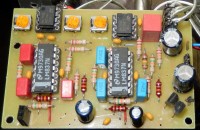
Active audio crossover filter

easy to made crossover
Active audio crossover filter
There are already many active crossover filters published and almost all contain many (expensive) components.
The filter presented here is a favorable exception: fewer components are required and need they not to be very accurate so that 'normal' components can be used.
These are the benefits that cling to the use of the state-variable filter.
After all, the most commonly used solution for a filter is the second order high- or lowpass filter consisting of 2 resistors and 2 capacitors and an opamp. That means 2 RC times in the circuit that also affect each other.
In the state-variable filter, all RC times are separated by an opamp so they can not affect each other.
This makes it possible to use inaccurate (but good) capacitors and set the correct RC time with 1% resistors. The 1% resistors are nowadays easy to get and much cheaper than 1% capacitors.
In addition, with 1 filter, both the high and the low frequencies can be separated so that less components are needed in total. Thus, with a single filter, a bi-amp amplifier can already be made. A three-way filter can be realized with 2 filters.
The state variable filter consists of a summing amplifier followed by a number of integrators in succession. The output of each integrator is fed back to the summing amplifier in the correct phase and intensity.
The number of integrators determines the order of the filter, the degree of feedback determines its characteristic.
The diagram below shows a third-order three-way filter.
And there is also a print layout as well:
A 4th order circuit looks almost the same:
And also the print has a lot of similarity.


Mises à jour de l'auteur