3 displays alarm-clock with TFT screen, Softwareupdate and RTC upgrade [170112-b]
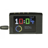
RTC and software update for Elektor project 170112 Three Display Clock
Software version 2.7.0 and RTC upgrade
For the alarm clock with 3-way display, the wish was expressed to be able to set more than just one alarm. Who wants to be woken up early on their day off when they are thinking about sleeping in again? So you just need to quickly add a few more alarms to the software. Those who develop software know that such assumptions, especially with existing code sometimes don't make the days easy. And sometimes one or the other has already heard the sentence "Someone has already started, it looked almost finished and shouldn't be much work......".
For the alarm clock with triple display it also meant that there was still a lot of work to be done, but not only the additional alarms should be included. With such projects it means to check what the previous developer has already started and whether the current status and the open points are to be taken from the project.
Nine alarms were selected because this quantity can be easily displayed. More alarms would mean running through multiple display pages. With nine adjustable alarms, the software now has the task of finding out which alarm is to be displayed next. Also alarms can now ring on a specific day of the week, or from Monday to Friday at a set time.
As soon as you start to customize the software, there comes another beginning of the sentence that adds a little more work: "While you're at it, you can't.... " . Also here a last minute wish was considered. The automatic dimming of the backlight can be switched off and three brightness levels are then available.
The operation of the alarm clock has changed a bit and a few menu items have been added.
That's why I've made the changes:
- 9 Adjustable alarms
- Alarms can be set to a day of the week or Monday to Friday
- Separate menu for alarms
- Optimized image composition
- RAM and computing time optimizations
- Backlight with automatic or manual brightness
- LDR Calibration
There are now two menus for operation. One for setting the alarms and one for setting the time and backlight.
To access the alarm menu, press the S2 key. This is only possible if no alarm is ringing. If an alarm rings, the S2 button has the function of the snooze button and lets the alarm ring again in 5 minutes.
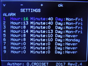
In the menu, the time and the day of the week on which this alarm is valid can be set for the individual alarms. The "Never" and "Mo-Fri" settings have special features. "Never" deactivates the alarm and "Mo-Fri" ensures that the alarm is active from Monday to Friday.
The S1 key is used to call up the settings for the time and the background lighting. New at this point is that no more alarms can be set and the item backlight has been added.
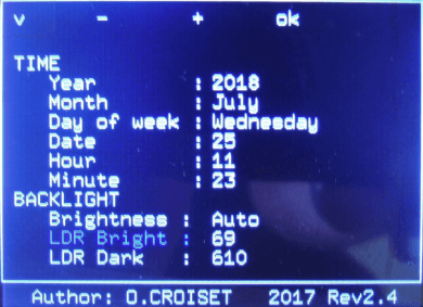
You can now choose whether the alarm clock should dim the light automatically or set one of three levels manually. Also the two menu points "LDR Bright" and "LDR Dark". These come factory calibrated, but you can easy change it your self. Navigate to the LDR Bright entry. To start calibration for your brightes spot press "OK". Now the value will be updating and if you found a bright sprot press "OK" again. The value is now stored. For the DLR Dark you can adjust this also the same way, but you need to find a dark spot. If you are done press "OK". The new values will now be takten to adjust the Backlight if you are in Auto mode.
Some insights to the softwarechanges
As we needed to add new functionality, here you can get some insights what tasks had to be sovled and how. The first and obvious one was the added new alarms.
When must the alarm clock ring?
To determine this, the alarm clock calculates every minute the remaining time until the next alarm rings. The alarm with the shortest time to ring is now the next one to be displayed. What sounds quite simple has a few small special features.Assuming it is 11:56 on a Friday and we have set the following alarms, for simplification we will only work with four entries like here:
| No. | Hour | Minute | Day |
| 1 | 11 | 55 | Mo-Fri |
| 2 | 11 | 59 | Tue |
| 3 | 08 | 00 | Never |
With alarm 1 we have the special feature that it is valid for Monday to Friday. So we need to see what day of the week we have. If the current day of the week is a Saturday or Sunday, it is assumed that alarm 1 is intended for a Monday when calculating. If it is not one of the two days of the week, we take that the alarm rings on the same day.
Now it's Friday and we have 11:56 AM. The above logic tells us that the alarm will ring on the same day, and yes, he must have done so. We remember that the time to ringing corresponds to 0 whole days, less than one day. Now let's look at the hours. Alarm 1 should ring in hour 11 and we have hour 11, so there are still 0 whole hours to ring. Now the minutes come. We've got minute 56 and we're supposed to ring 55 bells in minute 55. So there is still -1 minute left. The -1 at this point says that this alarm has already rung today and that we now have to make some corrections. So we subtract 60 minutes ( 1 hour) from our hours and add them to our minutes. That'll give us 59 minutes.
0 hours - 1 hour = -1 hour. Okay, the minutes are correct, but now the hours are negative. So we subtract 24 hours (one day) from our days and add them to our hours.
-1 hour + 24 hours = 23 hours. Well now the hours are positive again and we have to deduct another day. 0 whole days -1 day = -1 day. This is where it gets tricky. The alarm is valid from Monday to Friday. So if today is Monday, Tuesday, Wednesday or Thursday we can simply replace -1 with 0 and do nothing wrong. But we have Friday and since on Saturday the alarm should not ring we have to add three more days ( Saturday and Sunday + one borrowed ( the -1 )). So we come to a long time from :
2 days, 23 hours and 59 minutes until the alarm rings again. So that the AVR can count on it better will make from it a distance until the next ringing in minutes. So for this alarm, 4319 minutes.
For alarm 2 it is easier to calculate the distance because it is only active on one day of the week. First we charge again the whole days until the bell rings. We expect the weekdays to start at zero for Monday. In this case we have Tuesday ( 1 ) and Friday ( 4 ). We calculate 1-4 = -3 days. In this case, since there is only one weekday we have to add another week ( 7 days) again. So for the whole days -3+7 = 4 The alarm should ring in hour 11 and we have hour 11, so still 11-11 hours = 0 whole hours until ringing. The alarm is set to minute 59 and we have minute 56,so 59-56 = 3 whole minutes.
4 days, 0 hours and 3 minutes to ring, or 5763 minutes.
For alarm 2 the calculation is very simple, because this should never ring the distance is set to 65535 minutes (more than one week and therefore invalid)
At the end we get the following distances for the alarms:
Alarm 1: 4319 minutes
Alarm 2: 5763 minutes
Alarm 3: 65535 minutes
Now we look for the alarm with the shortest distance to ringing and take it. If there are alarms every 65535 minutes, then no alarm is active.
Backlight and the buttons
For the backlighting we use Timer1 as in the article, but to simplify the control we do not write directly into the registers of Timer1 in the actual sketch, but use the TimerOne library. The code for controlling Timer1 and generating the PWM for the background lighting are thus quite simple.…
Timer1.initialize(1000); // initialize timer1, and set it to 1000Hz
Timer1.pwm(9, 512); // setup pwm on pin 9, 50% duty cycle
Timer1.attachInterrupt(callback); // attaches callback() as a timer overflow interrupt
…
The "Timer1.initialize" specifies the period in microseconds, the library takes over the conversion into the appropriate register values for the AVR for us. To get a PWM signal at pin 9 or 10, the two hardware pins of the timer, we have to do this with "Timer1.pwm(Pin, DutyCycle)". The duty cycle runs here from 0 to 1023 and 50% correspond to the value 512, the last line is for the overflow interrupt. Each time timer 1 reaches the end of a period, an interrupt is triggered. We can now use " Timer1.attachInterrupt(callback); " to tell Timer1 that the function passed as parameter should be called from the interrupt, in this case 1000 times per second. This also means that the PWM for the display is controlled with 1000Hz. This makes the display flicker-free for the human eye. Timer1.initialize(1000); // initialize timer1, and set it to 1000Hz
Timer1.pwm(9, 512); // setup pwm on pin 9, 50% duty cycle
Timer1.attachInterrupt(callback); // attaches callback() as a timer overflow interrupt
…
One could now also come up with the idea of using the Timer2 for the key enquiry. However, this is not so easily possible. The beeping that the buzzer emits is controlled by the tone() function. In the background, it uses Timer2 to generate the desired sound. Now we still have Timer0, but this is used in the Delay functions and is not available.
Our keys on the board are read in and processed within the Timer1 interrupt. Since this function is to be called at about 100Hz, we must ensure in the callback that the function is only executed every 10th call.
Additionally, we have our buzzer which, when it rings, rings at the rhythm of one second, one second off, the ringing tone of itself. To get a stable change every second we use the callback in the Timer1 interrupt and make sure that the function for updating the output of our buzzers is called every second.
This is the code used for the callback
void callback()
{
static uint8_t prescale_touches = 0;
static uint8_t prescaler_buzzer=0;
if(prescale_touches>=10){
Button = Touches();
prescale_touches=0;
prescaler_buzzer++;
} else {
prescale_touches++;
}
if(prescaler_buzzer>=100){
Buzzer();
prescaler_buzzer=0;
}
}
{
static uint8_t prescale_touches = 0;
static uint8_t prescaler_buzzer=0;
if(prescale_touches>=10){
Button = Touches();
prescale_touches=0;
prescaler_buzzer++;
} else {
prescale_touches++;
}
if(prescaler_buzzer>=100){
Buzzer();
prescaler_buzzer=0;
}
}
We use two uint8_t variabels as divider. The first one divides by 10 and the second one is incremented every 10th call untill 100. With this chain we can divide by 1000 and only use an additional 1 Byte variable instead of a 2 Byte one if we directly divided by 1000 to get the second intervall.
Within our main we call every second the function backlight. In Auto-Mode this adjust depending on the value of the LDR the backlight brightness. As in this design the LDR is build as voltage devider using the internal AVR Pullup this leads to some effects we need to take care off. As the internall pullup has a value between 30k and 60k and du to production the value of the LDR at a given Lux varies, the voltage we messures divides between every clock a bit. If you build your own system with a LDR it's wise to use a resistor of a know value as pullup. An alternative for your own project may be also a BH1750FVI sensor.
With the given range the LDR has we convert the values to a scale of 0 to 255, where 255 is dark and 0 is bright. At the End we have to invert the values for the backlight as 0 is dark and 255 is bright. To do this 255 - [Scaled_Light_Value] will do the trick.
Optimizing
The Arduino code already needs about 30kB of our 32kB Flash and occupies 1192 bytes RAM of maximum 2000 bytes. A look at the potential savings can therefore do no harm.Variables need RAM and FLASH if they have initial values.
When looking into the code for the Arduino sketch, the first point is the variables. There we find e.g.
…
double x1Trait; // internal circle Cinqmin x
double y1Trait; // internal circle Cinqmin y
…
float x1precH = 120;
float x2precH = 120;
…
int myYear;
int myMonth;
…
As easy as it may be to work with float, double and int as a developer, it is not the easiest cost for AVR to calculate. Also, we may have used more RAM than necessary. The AVR compilers have a special feature for double and float. While modern architectures calculate with a double with 64Bit and with a float with 32Bit, the AVR Compiler (here AVRGCC) equates float and double for simplification. So this is a deceptive package and does not bring higher accuracy at the end of the day.double x1Trait; // internal circle Cinqmin x
double y1Trait; // internal circle Cinqmin y
…
float x1precH = 120;
float x2precH = 120;
…
int myYear;
int myMonth;
…
Also, the code on which many variables are declared with int falls. An int means we use two bytes for a variable and can store numbers from -32,768 to 32,767. This initial consideration is instructive to see if the code can be optimized in a few steps, so that we need less computing time and can minimize both RAM and FLASH consumption.
When developing code for a microcontroller or a microcontroller family, one should try to design the code so that all operations can be performed with the native width of the registers in the CPU. With the AVR, the registers are 8 bits wide (one byte) and we can add, subtract or multiply Atmega AVRs within one processor clock. But if we now have values that are more than one byte in size, the AVR takes longer. Here the compiler has to split the calculations into 8Bit operations. While all integer operations of the four basic arithmetic operations require effort, calculations with float or double represent a different degree of difficulty for the AVR. If now still functions such as sine or cosine are involved, our calculation quickly block several thousand CPU clocks.
Calculating with trigonometric functions only if necessary
Currently, the software requires considerable computing time for drawing on the display. One reason for this is the library used for the display. The ucglib makes it very easy for the developer to output with the AVR graphics, but unfortunately also at the expense of speed. In addition, the use of sin() and cos() is not conducive to speed. For a sin() calculation the AVR needs about 1650 cycles, for a cos() a similar number. If we now assume 12MHz which our AVR has, that means (12000000 Hz)/(1650 clocks per operation)=7272 operations per second. As already described in the article in the Elektor 5-2018, only the hands of the clock require 8 coordinates to be placed on imaginary circles. This means it is calculated with sin() and cos(). Besides the hands, the points of the seconds are also arranged in a circle, so sin() and cos() are needed again.If we look at the function "SecondeSecteur", a new point is drawn every 5 seconds. This requires sin() and cos() four times each. In the source code we see:
…
x_ext_Sec = ext_radius * cos(angleSec); x_ext_Sec = x_ext_Sec + xcenter ;
y_ext_Sec = ext_radius * sin(angleSec); y_ext_Sec = y_ext_Sec + ycenter ;
x_int_Sec = int_radius * cos(angleSec); x_int_Sec = x_int_Sec + xcenter ;
y_int_Sec = int_radius * sin(angleSec); y_int_Sec = y_int_Sec + ycenter ;
x_ext_SecPrec = ext_radius * cos(angleSecPrec); x_ext_SecPrec = x_ext_SecPrec + xcenter ;
y_ext_SecPrec = ext_radius * sin(angleSecPrec); y_ext_SecPrec = y_ext_SecPrec + ycenter ;
x_int_SecPrec = int_radius * cos(angleSecPrec); x_int_SecPrec = x_int_SecPrec + xcenter ;
y_int_SecPrec = int_radius * sin(angleSecPrec); y_int_SecPrec = y_int_SecPrec + ycenter ;
…
All variables are integer. Each multiplication of two int needs another 20 cycles. So we arrive at ( 1650*8 ) +( 8*20 ) = 13360 cycles neglecting the additions. At 12 MHz, we need 1.12 milliseconds. That's a lot more time and code. If we now consider that such a calculation is necessary every 5 seconds we arrive at 8*12 = 96 different calculations which are processed by the code at all. To save the microcontroller from calculating, we can calculate the necessary values in advancex_ext_Sec = ext_radius * cos(angleSec); x_ext_Sec = x_ext_Sec + xcenter ;
y_ext_Sec = ext_radius * sin(angleSec); y_ext_Sec = y_ext_Sec + ycenter ;
x_int_Sec = int_radius * cos(angleSec); x_int_Sec = x_int_Sec + xcenter ;
y_int_Sec = int_radius * sin(angleSec); y_int_Sec = y_int_Sec + ycenter ;
x_ext_SecPrec = ext_radius * cos(angleSecPrec); x_ext_SecPrec = x_ext_SecPrec + xcenter ;
y_ext_SecPrec = ext_radius * sin(angleSecPrec); y_ext_SecPrec = y_ext_SecPrec + ycenter ;
x_int_SecPrec = int_radius * cos(angleSecPrec); x_int_SecPrec = x_int_SecPrec + xcenter ;
y_int_SecPrec = int_radius * sin(angleSecPrec); y_int_SecPrec = y_int_SecPrec + ycenter ;
…
We can create a spreadsheet of our choice and get eight arrays with 12 values each. This allows us to reduce the time for calculations from several thousand cycles to less than 100. So we're ten times faster here. Although this doesn't save the lion's share of time for drawing, it shows that a little thinking and precalculation in AVR can save time and code. The same approach is used for the "AiguilleSecondes" function.
The same would be possible at other places for the minute and hour hands, but here ( 8*60 )+ (8*12*60) = 6240 values are necessary, because each hand has a different position every minute.
Don't duplicate work.
You can always write functions for drawing elements individually during development, e.g. when drawing the segments of our seven segment display. A correction or change makes it necessary that we have to adapt several functions. If you notice similar looking code parts, you should consider whether they can be combined to one function. This was done for the functions SegmentA(), SegmentB(),SegmentC(), SegmentD(), SegmentE(),SegmentF() and SegmentG(). Since the basic function is always the same, we can merge it into a segment function and let the parameters decide which segment we want to draw in which color. With existing code, such optimizations are sometimes difficult to make, as it can mean making major changes.Another place in the code is Cadran2(). There the multiple switch construct for the hours and minutes was replaced by a help function. This makes the actual function Cadran2() more compact.
Besides the pure avoidance of code, the execution, here the redrawing of numbers, can also be avoided. If the hour display does not change, why should I have the microcontroller redraw the same number once? However, in order to be able to compare this with each run of the function, it must be remembered which numbers we have drawn. This could now happen with global variables, or static variables can be used within the function. The last one was made in the function to remember what numbers were drawn. If the current time differs from the displayed time, only the part that has changed can now be updated. This ensures a much more pleasant update of the time.
Also something to note are the helper functions to print text on the lcd. You can see that we are using the
F("Your Text")
Macro for the print. This will put the string into flash. If we use a variabel in RAM this will be also put in FLASH and at the start copied into RAM, so we direktly use it from flash. But every text with this macro even if we have two times the same, will consume FLASH space. If we now put codelines that replicated ,e.g. in the menu, in functions we have only the text once in flash.
Debugging without Debugger
The easiest way would be to connect a debugger to the AtMega328P and start debugging. But with the Arduino IDE this is not intended and mostly a debugger for the AVR, like the AVR Dragon, is not always directly at hand.In the simplest case, a home remedy is an IO pin and an LED with pre-resistance. This can then be switched on and off at certain code points. The calculation effort for setting or deleting an LED is also very low. We use only one processor cycle.
Another common household remedy is the use of the USART. If the TX pin is not used, directly readable text can be output through a Serial.print(). Now the text output on the UART is very practical, but with 9600 baud, longer character strings take up considerable computing time and visibly slow down the program flow of the alarm clock. With the 12MHz quartz we can set 250000Baud without much effort and the USB to serial converters with CH340 or CH341 chip also have no problem to process this baud rate.
For debugging the code, a combination of USART and IO pin with Logicanalyzer was used. In addition to the "whether the pin changes, the time behavior can also be measured. Then help the USART to find out possible calculation errors with suitable printf() statements.
But what if debugging is no longer necessary? Each printf() would have to be removed manually from the code. It is easier for the preprocessor to do the work for us.
Here's what we can use:
define DEBUGPRINT( X ) Serial.print( X )
define DEBUGPRINT( X ) do{ }while( 1 == 0)
If we want to have the output active now, we use the first #define and can then use a DEBUGPRINT( "Test" ) in the code; let us output the text "Test". If we don't want any more expenditure, then we use the second #define. With the do-while, no output is executed on the USART by the compiler at the end and the do-while is completely optimized away during the set optimization.define DEBUGPRINT( X ) do{ }while( 1 == 0)
Optimizing the path is also what makes the use of an AVR-Dragon more difficult. When optimizing to the smallest size, the compiler only has to make sure that the result at the end of functions is correct. The way there can be designed by the compiler in such a way that the optimal execution path for it is run through. This doesn't have to have anything to do with the order of the commands we thought up, maybe even whole functions are omitted by the optimization.
But debugging and bugs or malfunctions due to optimization are a topic for an other day...
Use 12 MHz ATmega328P with the Arduino IDE
Using the Amtega328p with a 12 MHz oscillator requires a few changes in the IDE. In the "Arduino\hardware\arduino\avr"-folder we need to add a few lines to get the software for our clock. Put the following in the file##############################################################
clock.name=Elektor 3 Display Clock
clock.vid.0=0x2341
clock.pid.0=0x0043
clock.vid.1=0x2341
clock.pid.1=0x0001
clock.vid.2=0x2A03
clock.pid.2=0x0043
clock.vid.3=0x2341
clock.pid.3=0x0243
clock.upload.tool=avrdude
clock.upload.protocol=arduino
clock.upload.maximum_size=32256
clock.upload.maximum_data_size=2048
clock.upload.speed=115200
clock.bootloader.tool=avrdude
clock.bootloader.low_fuses=0xFF
clock.bootloader.high_fuses=0xDE
clock.bootloader.extended_fuses=0xFD
clock.bootloader.unlock_bits=0x3F
clock.bootloader.lock_bits=0x0F
clock.bootloader.file=optiboot/optiboot_atmega328.hex
clock.build.mcu=atmega328p
clock.build.f_cpu=12000000L
clock.build.board=AVR_UNO
clock.build.core=arduino
clock.build.variant=standard
Now you can select this board and be able to compile the scetch with the right cpu speed.
Sometimes time matters
The clock uses a DS1302 with an external crystal. Given the fact that the componets choosen are reasonibly you still get 100ppm or even more drift in the timebase. This means if we take the 100ppm for example we end up with ~5 Minutes a month the clock may went into the wrong direction. This can be done better, and therefor we build a DS1302 dropin replacement that will give you a max drift of 20ppm, which menas you may have a max offset of 51 seconds am month.
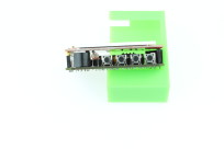
The PCB itself is discribed here. To install it you have to do some modifications to the PCB of the clock. The first method is to remove the DS1302 DIP-8 version and the DIP socket form the PCB and solder afterwards the new DS1302 PCB to the clock. This is shown here:

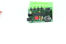
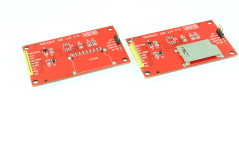
Also you have the option to remove the SD-Card-Socket from the display. This leaves you the option te reuse the DIP socket ans also the SD-Card-Socket is not connected to the AVR at all, so it's not a big lost and easy to remove. The results of this are shown here:


Discussion (4 commentaire(s))