

Adieu aux stéréotypes de codage de micrologiciels: Alternatives pratiques
sur

Le stéréotype usuel de codage de micrologiciel peut conduire à des perturbations opérationnelles, obligeant les développeurs à revenir sur leur programmation. Que se passe-t-il si votre microcontrôleur perd la connexion au réseau ou fait face à un conflit d’adresse IP ? Dans cet article, nous repensons les pratiques conventionnelles de codage et explorons les solutions efficaces pour augmenter la fiabilité et pour réduire les coûts des projets embarqués.
Les nombreux projets embarqués que je découvre dans les médias fournissent des solutions brillantes aux développeurs, mais ne parviennent pas à répondre aux questions fondamentales. Que faire si le microcontrôleur (MCU) perd la connectivité au réseau pendant l'exécution ? Comment résoudre les conflits d’adressage IP dans le réseau local (LAN) ? Est-il obligatoire d'utiliser une horloge RTC (Real Time Clock) pour maintenir un timing précis ? Les ajustements d’horaire exigent-ils une intervention de l’utilisateur ? Devons-nous alimenter les capteurs de façon permanente durant le fonctionnement du microcontrôleur ?
Nous devons prendre du recul et réfléchir lorsqu’il s’agit du codage conventionnel stéréotypé ! Dans cet article, je passe en revue les méthodes conventionnelles de codage des microcontrôleurs qui manquent d’aspects pratiques et demandent de temps en temps l’intervention de l’utilisateur pour résoudre des dysfonctionnements opérationnels. Dans de tels cas, des boutons de réglage et un afficheur sont nécessaires afin de contrôler, remettre à zéro, prérégler ou interrompre le microcontrôleur puis prendre une action corrective. Parallèlement à l’interfaçage des capteurs, la prise en compte des boutons ou afficheurs, facilitant l’intervention de l’utilisateur, peut être problématique lorsque les entrées/sorties standards sont en nombre limité.
Lorsque l’on utilise l’EDI Arduino, deux parties distinctes du code doivent être considérées, l’initialisation setup() et la boucle loop(). La première section est dédiée à l’initialisation du microcontrôleur, des périphériques et capteurs qui y sont reliés. La deuxième partie renferme les activités de traitement pouvant lire les capteurs et en déduire les actions à entreprendre. L’affectation de ces sections de façon conventionnelle désoriente les développeurs qui leur accordent leur confiance pour un fonctionnement parfait, mais qui sont surpris lorsque subviennent des dysfonctionnements pouvant les obliger à revoir leurs règles de conception. Il m’est arrivé de devoir faire face à de telles situations, me trouvant confronté avec les interrogations mentionnées. Toutefois, j’ai pu aboutir à des solutions efficaces pour résoudre les dysfonctionnements opérationnels et réduire le coût de mise en œuvre de mes projets, en intégrant quelques actions traditionnelles de la partie setup() dans la boucle loop(). Je vais élaborer cette stratégie dans l’étude de cas suivante.
Limiter la configuration Wifi à la section setup()
Lorsque le point d’accès est réinitialisé sur intervention de l’utilisateur, ou à la suite d’une remise sous tension, le microcontrôleur utilisé perd sa connexion au réseau local et doit redémarrer, de façon à exécuter à nouveau la section setup() pour réinitialiser la connexion Wi-Fi. Ainsi, la vérification de l’état de la connexion Wi-Fi devrait être régulièrement effectuée dans la boucle loop() et permettre de réagir en conséquence, suite à une perte de connectivité avec le point d’accès. Par ailleurs, la perte de connexion avec le réseau Internet est une autre situation qui doit être décelée pour les applications utilisant le web, même si la liaison Wi-Fi est valide. De telles stratégies sont rarement abordées dans les projets publiés qui semblent pouvoir s’appuyer sur la disponibilité d’une intervention humaine.
Heureusement, l’ESP8266 possède une bibliothèque Wifi intéressante, l’ESP8266WiFi [1][2], comportant une multitude de fonctions et capabilités rarement disponibles dans les projets décrits. Le site web Random Nerd Tutorials a examiné les alternatives de reconnexion sans fil fournies par cette bibliothèque. Une combinaison des instructions suivantes dans la section setup() fera l'affaire :
WiFi.setAutoReconnect(true);
WiFi.persistent(true);
En outre, la vérification de l’état de la connexion sans-fil dans la section loop() permet de prendre une action correctrice, comme par exemple le redémarrage du microcontrôleur. Le code de la figure 1 est régulièrement utilisé dans la section setup() mais peut être également utilisé dans la section loop(), en le modifiant légèrement.
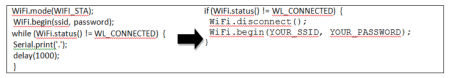
Le site Random Nerd Tutorials propose également une alternative basée sur les interruptions logicielles pour la détection des pertes de connexion et leur rétablissement. Avec un ESP8266, j’ai défini une approche différente pour vérifier l’état de la connectivité réseau. Je programme le microcontrôleur afin qu’il vérifie régulièrement la liaison au point d’accès Wi-Fi dans la section loop() par la fonction "ping", en utilisant ping(gateway_IP) de la bibliothèque ESP8266Ping. Cela est souvent nommé “Ping for Life”(“Ping éternel”), par les administrateurs de réseaux qui l’utilisent pour vérifier l’état d‘une connexion et la maintenir active, en évitant les dépassements de délais (Timeouts). Si le "ping" échoue, je force le redémarrage du microcontrôleur et tente une connexion avec un point d’accès secondaire. J’utilise également cette méthode pour vérifier l’accès à Internet, mais en réalisant un "ping" vers un serveur DNS tel que le serveur Google <8.8.4.4> au lieu du routeur Wi-Fi local, en utilisant la fonction ping(primaryDNS_IP). Si cette action régulière échoue, le microcontrôleur redémarre afin de se relier à un point d’accès ayant une liaison Internet active. J’inclus la bibliothèque ESP8266Ping dans mon sketch afin de pouvoir utiliser cette approche, comme dans le code du listage 1.
Listing 1: Ping of Life implementation for WLAN gateway and a global DNS server.
#include <ESP8266WiFi.h>
#include <ESP8266Ping.h>
IPAddress local_IP(192, 168, 1, 180);
IPAddress subnet(255, 255, 255, 0); // Subnet Mask
IPAddress gateway(192, 168, 1, 1); // Default Gateway
IPAddress primaryDNS(8, 8, 4, 4);
IPAddress secondaryDNS(8, 8, 8, 8);
// place this code segment in the loop() section for periodic checks
if (Ping.ping(gateway)) {
Serial.println("Ping gateway Success!!");
} else {
Serial.println("Gateway Ping Error!!");
ESP.restart();
}
// place this code segment in the loop() section for periodic checks
if (Ping.ping(primaryDNS)) {
Serial.println("Ping DNS Success!!");
} else {
Serial.println("DNS Ping Error!!");
ESP.restart();
}
Le redémarrage du microcontrôleur ESP8266 est assuré en appelant la fonction ESP.restart(). Cette fonction est incluse par défaut dans la plateforme ESP de l’IDE Arduino. Afin de pouvoir basculer vers un point d’accès différent lors du redémarrage, l’utilisateur peut vérifier la connectivité avec les tous les points d’accès disponibles en utilisant la même approche par "ping" et réaliser la connexion avec un point d’accès local valide dans la section setup(). Le listage 1 comporte les parties de code qui vérifient la connectivité avec les points d’accès locaux ainsi que l’accès à Internet.
Utilisation d’un module horloge temps-réel (RTC) pour le maintien de l’heure
Grâce à sa batterie de secours, qui maintient en permanence son fonctionnement, un module RTC assure la continuité du fonctionnement de son horloge quel que soit l’état du microcontrôleur auquel il est associé. Lors de chaque redémarrage du microcontrôleur, il transmet l’heure courante depuis l’horloge RTC et le fait régulièrement pour mettre à jour ses variables d’heure. De nombreux microcontrôleurs possèdent des temporisateurs internes capables de maintenir un comptage de millisecondes depuis le dernier redémarrage. J’aime les utiliser dans mon code, pour maintenir à jour les variables d’heure, durant le fonctionnement du microcontrôleur. Si le microcontrôleur peut être relié à Internet, il est intéressant d’accéder à un serveur NTP pour acquérir l’heure précise au redémarrage. J’utilise ces deux stratégies lors de l’initialisation, et durant le fonctionnement de mes modules ESP8266. Dans la section setup(), j’accède un serveur NTP pour acquérir l’heure courante lors du redémarrage, et dans la boucle loop(), j’utilise la fonction millis() pour mettre à jour l’heure courante. J’accède également à un serveur NTP de façon régulière dans la boucle loop() afin de réajuster l’heure maintenue par mon programme et compenser toute déviation qui pourrait se produire. Cette stratégie me permet d’éviter l’intégration d’un module RTC dans mes projets, réduisant les Entrées/Sorties utilisées et la consommation énergétique.
Dans l’extrait de code suivant, je montre comment l’on accède à un serveur NTP et maintien le minuteur d’horloge local pour qu’il délivre une heure précise, sans utiliser d’horloge RTC. J’ai créé deux fonctions pour manipuler l’horloge : getNtpTime() pour mettre à jour l’horloge à partir d’un accès NTP (voir listage 2) et la fonction update_time() pour manipuler le compteur interne du microcontrôleur (voir listage 3).
Listing 2: Update MCU clock while NTP syncing.
void getNtpTime() {
epochTime = timeClient.getEpochTime();
Serial.print("Epoch Time: ");
Serial.println(epochTime);
formattedTime = timeClient.getFormattedTime();
Serial.print("Formatted Time: ");
Serial.println(formattedTime);
currentHour = timeClient.getHours();
Serial.print("Hour: ");
Serial.println(currentHour);
currentMinute = timeClient.getMinutes();
Serial.print("Minutes: ");
Serial.println(currentMinute);
currentSecond = timeClient.getSeconds();
Serial.print("Seconds: ");
Serial.println(currentSecond);
weekDay = weekDays[timeClient.getDay()];
Serial.print("Week Day: ");
Serial.println(weekDay);
//Get a time structure
struct tm *ptm = gmtime((time_t *)&epochTime);
monthDay = ptm->tm_mday;
Serial.print("Month day: ");
Serial.println(monthDay);
currentMonth = ptm->tm_mon + 1;
Serial.print("Month: ");
Serial.println(currentMonth);
currentMonthName = months[currentMonth - 1];
Serial.print("Month name: ");
Serial.println(currentMonthName);
currentYear = ptm->tm_year + 1900;
Serial.print("Year: ");
Serial.println(currentYear);
//Print complete date:
currentDate = String(currentYear) + "-"
+ String(currentMonth) + "-" + String(monthDay);
Serial.print("Current date: ");
Serial.println(currentDate);
Serial.println("");
}
Listing 3: MCU internal timer update of the clock.
void update_time() {
int lapse = millis() - oldSec; // passed milliseconds since last clock update
if (lapse >= 1000) { // add passed seconds to clock reading
oldSec = millis();
currentSecond += lapse/1000;
if (currentSecond >= 60) { // add a minute for every 60 passed seconds
currentSecond -= 60;
++currentMinute;
if (currentMinute >= 60) { // add an hour for every 60 passed minutes
currentMinute -= 60;
++currentHour;
if (currentHour >= 24) { // adjust clock for AM transition
currentHour -= 24;
}
}
}
}
String hr, min;
if (currentHour < 10) hr = "0" + String(currentHour);
else hr = String(currentHour);
if (currentMinute < 10) min = "0" + String(currentMinute);
else min = String(currentMinute);
formattedTime = hr + ":" + min;
}
Dans la boucle loop(), j’appelle la première fonction toutes les heures afin de compenser toute variation de l’horloge, et j’appelle la seconde chaque minute pour mettre à jour les heures et minutes de l’horloge. Afin d'initialiser l'horloge du microcontrôleur lors du redémarrage, j'appelle la fonction NTP une fois dans la section setup() et déclare les variables globales nécessaires pour afficher la date et l'heure actuelles dans le traitement (voir listage 4). Cette séquence se substitue avec précision à l’utilisation d’un module RTC. De ce fait, avec regret, je me suis séparé de mon stock de modules RTC depuis que cette stratégie a porté ses fruits.
Listing 4: Sketch initialization with libraries and global variables for time processing.
// Define NTP Client to get time
#include <NTPClient.h>
#define NTPUPDATE 3600000 // frequency of accessing the NTP, every hour
const long utcOffsetInSeconds = 7200; // GMT +2
float oldSec = 0; // passed seconds since last reboot
WiFiUDP ntpUDP; // required UDP access by NTP client
NTPClient timeClient(ntpUDP, "pool.ntp.org"); // my chosen NTP server
time_t epochTime;
String formattedTime, weekDay, currentMonthName, currentDate;
int currentHour, currentMinute, currentSecond, monthDay, currentMonth, currentYear;
//Week Days
String weekDays[7] = { "Sunday", "Monday", "Tuesday", "Wednesday", "Thursday", "Friday", "Saturday" };
//Month names
String months[12] = { "January", "February", "March", "April", "May", "June", "July", "August", "September", "October", "November", "December" };
// Variables to save date and time
String formattedDate;
String dayStamp;
String timeStamp;
Adressage dynamique des serveurs web basés sur des microcontrôleurs
Chaque fois qu’un serveur web est démarré sur un matériel dont l’adresse IP est assignée dynamiquement, l’utilisateur doit obtenir son adresse IP à chaque redémarrage, afin de la transmettre à ses clients web. Une telle configuration réseau nécessite un point d’accès avec DHCP, comme dans le listage 5, sans la partie WiFi.config() (figure 2).
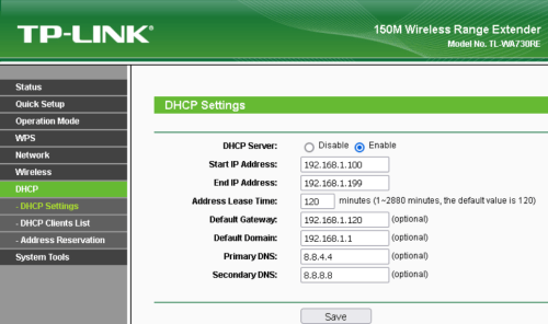
d’adresses IP est spécifiée, en plus des paramètres d’accès à Internet.
Toutefois, maintenir de cette façon la connexion au LAN des appareils est fastidieuse et demande d’être réétudiée. C’est pourquoi, j’ai tendance à utiliser une adresse IP fixe pour les serveurs web dans mon réseau personnel, afin de faciliter la maintenance de mes clients web répartis autour de mon serveur IoT (Internet des Objets). Le listage 5 montre un exemple dans lequel je paramètre les informations d’identification statiques dans le contrôleur d’éclairage de mon jardin.
Listing 5: Fixed WLAN network credentials.
IPAddress local_IP(192, 168, 1, 140); // MCU fixed IP address
IPAddress subnet(255, 255, 255, 0); // Subnet Mask
IPAddress gateway(192, 168, 1, 1); // Default Gateway
IPAddress primaryDNS(8, 8, 4, 4);
IPAddress secondaryDNS(8, 8, 8, 8);
const char *ssid = "YOUR_SSID";
const char *password = "YOUR_PASSWORD ";
void setup() {
WiFi.mode(WIFI_STA);
// Configure static wlan credentials, remove this segment for dynamic allocation
if (!WiFi.config(local_IP, gateway, subnet, primaryDNS)) {
Serial.println("STA Failed to configure");
}
else {
Serial.println("Static IP Configuration Succeeded!");
}
// Connect to Wi-Fi network with SSID and password
WiFi.begin(ssid, password);
while (WiFi.status() != WL_CONNECTED) {
delay(500);
Serial.print(".");
}
// . . . . .
} // setup() end
L’accès à un serveur web, en utilisant son nom de domaine, plutôt que son adresse IP, est une autre possibilité pour résoudre les difficultés d’accès au serveur. Ainsi, pour un microcontrôleur auquel l’adresse IP est affectée dynamiquement, j’utilise la bibliothèque mDNS propre à l’ESP8266 pour assigner un nom de domaine au serveur implémenté sur l’ESP et je l’utilise dans les clients web utilisant la méthode Bonjouri> pour accéder au serveur. NDLR : Bonjour est un protocole Zeroconf créé par Apple permettant une configuration aisée des appareils se trouvant sur un réseau local. J’utilise également cette méthode dans le cas des serveurs avec adresse IP fixe, car cela simplifie l’accès aux serveurs web pour les utilisateurs non techniciens, qui sont peu familiarisés avec l’adressage IP. La figure 3 montre comment j’accède au contrôleur d’éclairage de mon jardin à partir d’un navigateur web, en utilisant soit son nom DNS, soit son adresse IP fixe.

assigné par DNS ou son adresse IP fixe <192.168.1.140>.
Le listage 6 montre le codage nécessaire pour nommer le microcontrôleur dans le réseau WLAN où MDNS est l’objet simplifiant les fonctions mDNS pour l’activation et le maintien du nom réseau du microcontrôleur.
Listing 6: Assigning a network name for the MCU for easy accessibility in Bonjour-enabled web clients.
#include <ESP8266WebServer.h>
#include <ESP8266mDNS.h>
ESP8266WebServer server3(80); // mDNS activation server
String newHostname = "garden1"; // my garden controller network name
// shall be automatically appended with .local
// to form a legitimate domain name
void setup() {
// . . . . .
if (!MDNS.begin(newHostname)) {
Serial.println("Error setting up MDNS responder!");
while (1) {
delay(1000);
}
}
Serial.println("mDNS responder started");
// Start the server
server3.begin();
Serial.println("TCP server started for mDNS activation!");
// Add service to MDNS-SD
MDNS.addService("http", "tcp", 80);
. . . . . . . . .
} // setup() end
void loop() {
MDNS.update();
// . . . . .
} // loop() end
Conflit d’adressage IP d’un microcontrôleur dans le réseau local
Lorsqu’un réseau IoT croît de façon importante tout en utilisant l’allocation IP fixe, il est important de considérer la possibilité d’affecter par erreur la même adresse IP à plusieurs contrôleurs. Une telle situation provoque des conflits d’adressage IP dans le réseau, rendant les dispositifs en conflit inaccessibles à partir du réseau (voir la figure 4). Il est évident qu’une gestion centralisée des ressources du réseau peut éviter une telle situation, mais ce n’est pas toujours la règle de base.
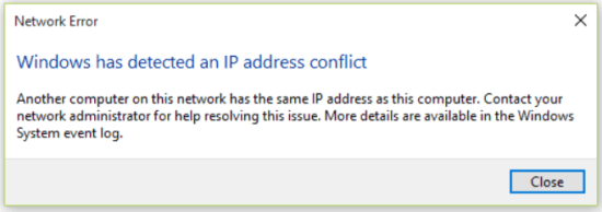
non seulement pour les systèmes embarqués mais également pour les ressources de calcul.
Lors du redémarrage, le microcontrôleur émet une requête d’adresse IP dynamique et "ping" l’adresse IP fixe définie pour s’assurer qu’elle n’est pas assignée à un dispositif du réseau LAN. Le microcontrôleur initialise ensuite une connexion à l’adresse IP fixe définie dans la section setup(). Dans le listage 7, j’envoie une commande "ping" à l’adresse IP fixe locale déclarée dans le Listing 1, avant de l’affecter au microcontrôleur. Préalablement à l’appel de cette partie du code, le microcontrôleur devra se connecter au LAN en utilisant une adresse IP temporairement délivrée par le serveur DHCP. Si le "ping" échoue, je peux alors être certain que l’adresse IP fixe définie peut être utilisée en toute sécurité. Dans le cas contraire, le microcontrôleur devra redémarrer afin de revérifier et résoudre le conflit à intervalle d’une minute.
Listing 7: Pinging IP conflicting network resources.
#include <ESP8266WiFi.h>
#include <ESP8266Ping.h>
IPAddress local_IP(192, 168, 1, 140); // MCU fixed IP address
IPAddress subnet(255, 255, 255, 0); // Subnet Mask
IPAddress gateway(192, 168, 1, 1); // Default Gateway
IPAddress primaryDNS(8, 8, 4, 4);
IPAddress secondaryDNS(8, 8, 8, 8);
const char *ssid = "YOUR_SSID";
const char *password = "YOUR_PASSWORD ";
void setup() {
// . . . . .
WiFi.mode(WIFI_STA);
// Connect to Wi-Fi network with SSID and password using DHCP assigned IP
WiFi.begin(ssid, password);
while (WiFi.status() != WL_CONNECTED) {
delay(500);
Serial.print(".");
} // while end
// check IP conflicts, restart MCU if conflicts exist
if (Ping.ping(local_IP)) {
Serial.println("IP conflict detected!!");
Delay(60000); // wait for a minute then reboot
ESP.restart();
} else {
Serial.println("No IP conflict detected!!");
// Configure static wlan credentials
if (!WiFi.config(local_IP, gateway, subnet, primaryDNS)) {
Serial.println("STA Failed to configure");
} else {
Serial.println("Static IP Configuration Succeeded!");
// Connect to Wi-Fi network with SSID and password
WiFi.begin(ssid, password);
while (WiFi.status() != WL_CONNECTED) {
delay(500);
Serial.print(".");
} // while end
} // else end
} // else end
// . . . . .
} // setup() end
Économie d’énergie des capteurs et du microcontrôleur
La consommation énergétique devient une préoccupation pour les systèmes embarqués fonctionnant à partir de batteries. Le pilotage des capteurs et actuateurs peut vider la batterie, même lorsque le microcontrôleur est en mode veille. Par construction, un moteur pas-à-pas consomme de l’énergie, même lorsqu’il est inactif. Les projets publiés adoptent un circuit simple composé de deux transistors et trois résistances pour contrôler la tension continue 5 V utilisée pour alimenter l’ensemble des charges, en utilisant une broche d’entrée/sortie.
La même approche peut s’appliquer aux capteurs pilotés pas le microcontrôleur, qui sont accédés périodiquement, ou en réponse à une intervention de l’utilisateur. J’ai conçu un circuit plus simple pour contrôler l’alimentation en courant continu des capteurs ou leur liaison à la ligne de masse commune. Dans cet article, je présente un circuit qui coupe la liaison des capteurs à la masse, utilisant un transistor NPN pouvant accepter une intensité de 1,5 A. La base du transistor BD139 est commandée directement par une broche GPIO du microcontrôleur (voir la figure 5).
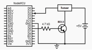
par le microcontrôleur.
Lorsque cette broche est au niveau haut (D6 dans la figure), la tension de polarisation de la base du transistor le met à l’état "saturé", son collecteur et son émetteur étant reliés, avec une chute de tension de saturation négligeable. La masse commune des capteurs étant reliée au collecteur du transistor, les capteurs sont tous alimentés. Lorsque la broche d’entrée/sortie utilisée est au niveau bas, le transistor est à l’état bloqué, interrompant l’alimentation des capteurs.
Le lecteur pourra envisager une économie d’énergie plus importante en réduisant le temps de fonctionnement du microcontrôleur si les contraintes exposées s’appliquent également au microcontrôleur. Un microcontrôleur possède différents modes de - veille.
Questions ou commentaires ?
Envoyez un courriel à l'auteur drgamallabib@yahoo.co.uk, ou contactez Elektor redaction@elektor.fr.
Discussion (2 commentaire(s))
Christophe Vermeulen il y a 1 mois
bob.autochtone@gmail.com il y a 1 mois