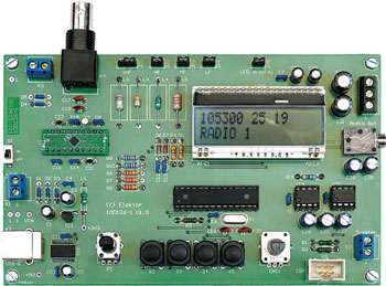
The Elektor DSP radio (1)
DSP world receiver with USB interface

Ceci est un article RÉSERVÉ AUX MEMBRES. Vous avez besoin d'un abonnement pour lire cet article.
- Accès illimité aux articles réservés aux membres
- 3 nouvelles éditions du magazine Elektor (numériques)
- Plus de 5000 fichiers Gerber
- 20% de réduction pour les membres sur les e-books (sur elektor.fr)
- 10% de réduction pour les membres sur les produits (sur elektor.fr)
Disponible à partir de 6,33 € par mois.
Qu'est-ce que la Uniquement membres
Elektor s'engage à fournir des contenus de haute qualité dans le domaine de l'électronique, servant ainsi des dizaines de milliers de membres payants. Dans le cadre de cet engagement, Elektor a lancé l'initiative Premium, qui propose des articles en ligne exclusifs pour les membres, parfois même avant leur publication dans le magazine.
Chaque jour, les membres peuvent accéder à des articles approfondis qui présentent le meilleur des contenus Premium d'Elektor.
Cette initiative vise à récompenser les membres en leur offrant un accès anticipé. Une fois connecté, vous pouvez facilement profiter de ce contenu exclusif et participer aux discussions sur les projets présentés.
Alors que Premium élargit les ressources disponibles, Elektor continuera à fournir une richesse d'informations gratuites.
Rejoignez dès aujourd'hui la communauté Elektor pour profiter de Premium et d'autres avantages !
Matériaux
Fichier Gerber
Le circuit imprimé de cet article est disponible sous forme d’un ou plusieurs fichiers Gerber. Seuls les membres de la communauté d’Elektor peuvent télécharger gratuitement ce(s) fichier(s). Avec ce(s) fichier(s), vous pouvez réaliser vous-même le circuit imprimé ou bien le faire faire.
Si vous souhaitez passer par un service en ligne, nous vous recommandons notre partenaire Eurocircuits. Nous faisons régulièrement appel à Eurocircuits pour nos prototypes et notre production en série.
L’utilisation de nos fichiers Gerber est protégée par une licence Creative Commons modifiée. Creative Commons offre aux auteurs, scientifiques, enseignants et autres créateurs la liberté de gérer avec souplesse leurs droits d’auteur, sans perdre leurs droits réservés.
Info supplémentaire / Mise à jour
- no set-up adjustments required
- Si4735 DSP receiver IC
- ATmega168 microcontroller
- USB interface using FT232R
- backlit 2 x 16 LCD panel
- battery voltage 4.8 to 6 V
- current consumption approximately 50 mA
- 3.3 V internal power supply
- power from PC over USB interface
- stereo audio output
- stereo audio amplifier (2 x LM386)
- RDS display
- AM from 153 kHz to 21.85 MHz
- automatic station search
- antenna signal strength indication in dBµV
- signal strength meter connection
- diode switching of AM band
- automatic tuning of AM resonant circuit
- switchable AM bandwidth
- optional PC control over USB
- tuning using rotary encoder
- four control pushbuttons
- station memory (30 AM presets and 30 FM presets)
- open-source firmware (free download)
- in-system programming interface
- printed circuit board available ready-populated and tested
Composants
La nomenclature (BOM, Bill of Materials) fournie par Elektor est une liste aussi complète que possible de fournisseurs pour les projets du labo d’Elektor. Elle est plus détaillée que la liste publiée dans le magazine. En outre, elle est mise à jour si nécessaire.En tant que lecteur, vous pouvez télécharger cette nomenclature ici.
Liste des composants
(5%, 0.25 W)
R1-R3 = 100Ohm
R4,R5 = 470Ohm
R6-R8 = 22kOhm
R9,R10 = 1kOhm
R11 = 47Ohm
R12,R13 = 10Ohm
P1 = 10kOhm trimpot, linear, vertical adjustment, PCB mount, ALPS type RK09K11310KB (Farnell # 1191725)
Capacitors
C1,C23,C24,C26,C27 = 1uF 16V, electrolytic, radial, 5mm diameter
C2, C3 = 4.7uF 16V, electrolytic, radial, 5mm diameter
C4-C16 = 100nF, ceramic capacitor, 2.54 mm lead pitch
C17, C18 = 47pF, ceramic capacitor, NP0, 5.08mm lead pitch
C19, C20 = 22pF, ceramic capacitor, NP0, 5.08mm lead pitch
C21, C22 = 12pF, ceramic capacitor, NP0, 5.08mm lead pitch
C25 = 100uF 16V, electrolytic, radial, 6.3mm diameter
C28, C29 = 47uF 16 V, electrolytic, radial, 6.3mm diameter
C30, C31 = 470uF 16 V, electrolytic, radial, 8.0mm diameter
C32, C33 = 100nF, polyester (MKT), 5.08 mm lead pitch
Inductors
L1 = 10uH (Fine Inductors Fastron type SMCC-100X-YY)
L2 = 0.1uH (Fine Inductors Fastron type SMCC-R10X-YY)
L3 = 4.7uH (Fine Inductors Fastron type SMCC-4R7X-YY)
L4 = 220uH (Fine Inductors Fastron type SMCC-221X-YY)
L5 = 2.2mH (Fine Inductors Fastron type SMCC-222X-YY)
Semiconductors
D1-D5 = BAT48, Schottky diode, 330 mW, DO-35
D6,D7 = 1N4148
IC1 = LP2950ACZ-3.3/NOPB, LDO voltage regulator, 3.3 V, 100 mA, TO-92
IC2 = FT232RL, USB to serial UART interface, FTDI, SSOP-28
IC3 = ATmega168PA-PU, PDIP-28, programmed, Elektor # 100126-41)
IC4, IC5 = LM386N-1, DIL-8
Y1 = Si4735 broadcast AM/FM/SW/LW radio receiver carrier board, DIL-20, Elektor # 090740-71
Miscellaneous
ENC1 = Rotary encoder, vertical, 12 ppr, ALPS type EC12E1220401 (Farnell # 1520809)
JP1 = 3-way pinheader, 2.54 mm lead pitch + jumper
JP2-JP5 = 2-way pinheader, 2.54 mm lead pitch + jumper
K1-K3 = 2-way, screw-type terminal block, 5mm lead pitch
K4 = BNC connector 50 ohms, black, PCB, mount, Tyco Electronics type 1-1634612-0 (right angle);
type 1-1634505-0 (vertical) (Farnell # 1020957; # 1020960)
K5 = 3-way PCB terminal block, 5mm lead pitch
K6 = jack socket, 3.5mm, stereo (Farnell # 1267400)
K7 = USB socket type B, PCB mount
K8 = 6-way (2x3) header, wire-to-board (Farnell # 1096984)
LCD1 = Alphanumeric LCD 2x16, (Electronic Assembly type EA DOGM162W-A) + LED blue backlight (type EA LED55X31-B)
S1 = slide switch, SPDT, C&K type OS102011MS2QN1 (Farnell # 1201430)
S2-S5 = Tactile switch, SPNO, MULTIMEC type 3FTL6 (Farnell # 1132885) + elevation caps
X1 = 8MHz quartz crystal, low-profile, case type HC49
X2 = 32.768 kHz quartz crystal, cylindrical case (3x8 mm)
2 pcs IC socket, DIL-8
1 pc IC socket, DIL-28 narrow body
Sockets for LCD elevation
PCB, bare, Elektor # 100126-1
PCB ready assembled and tested, Elektor # 100126-91


Discussion (0 commentaire(s))